
86-025-5119 7362

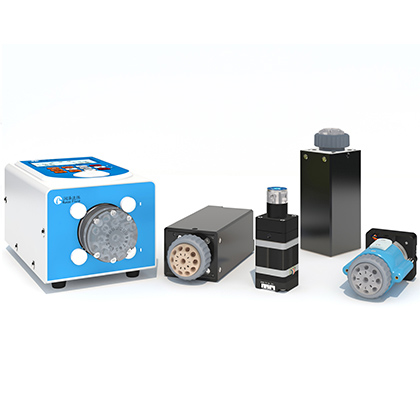
The RP-01 plunger pump is a compact 6 mL metering component for OEM instruments that need controlled aspiration and dispensing within a defined stroke. Selecting it requires more than checking nominal volume. The engineer must match the pump head, port arrangement, fluid-contact materials, pressure limits, control electronics, and expected operating cycle to the complete fluid path. The published data support precise decisions at the rated stroke under stated test conditions, but they do not replace application testing with the actual liquid, tubing, valves, fittings, and control sequence.
This guide organizes the verified catalog data into a practical selection process. It also separates published specifications from values that are not available in the source documents, such as performance with a particular reagent, maximum acceptable particle size, or a universal flow rate under every pressure condition. That distinction helps OEM teams define a test plan before committing the pump to an analyzer, sampler, or biological instrument.
Choose the RP-01 when a 6 mL stroke, compact packaging, 1/4-28 UNF fluid ports, and optional integrated drive or solenoid configurations fit the instrument. The catalog lists liquid-volume accuracy error of no more than 1% and repeatability error of 0.3% to 0.7%, both at the rated stroke. It also lists a three-million-cycle no-leak life test using pure water, where one rated stroke counts as one cycle. Treat these as catalog test results, not guarantees for every liquid or duty cycle. Verify chemical compatibility, pressure, dead volume, installation orientation, communications, and real-cycle performance on the assembled system.
The catalog identifies a 6 mL capacity, a 19.1 mm rated stroke with 3,820 control steps, a 0.005 mm control resolution, and a stated minimum injection increment of 1.5707 microliters. The maximum motor speed is 500 rpm, corresponding to a listed linear-speed range of 0.017 to 8.33 mm/s. Rated-stroke travel time is published as 2.292 seconds at 500 rpm to 1,146 seconds at 1 rpm. These figures describe the mechanical operating envelope. Actual delivered flow depends on the programmed movement, fluid path compliance, valve timing, pressure, trapped gas, and the behavior of the process liquid.
Selection Item | Published Value | Engineering Use |
Capacity | 6 mL | All listed RP-01 configurations |
Rated stroke | 19.1 mm and 3,820 steps | Use rated-stroke conditions when comparing catalog accuracy |
Control resolution | 0.005 mm and 1.5707 uL | Published mechanical control increment |
Accuracy | Error no more than 1% | Specified at rated stroke |
Repeatability | 0.3% to 0.7% error | Specified at rated stroke |
Pressure reference | Positive 0 to 0.5 MPa; negative 0 to 0.06 MPa | Catalog reference values; confirm system conditions |
Fluid interface | 1/4-28 UNF female thread | Check fitting and tube dimensions |
Power | DC 24 V and 1.5 A | Published for the product configuration |
Environment | 5 to 55 C; below 80% RH, non-condensing | Do not infer liquid temperature limits from ambient limits |
The product list includes single-port and two-port pump heads, with versions that omit or include the encoder and drive. A two-port version with a solenoid valve is also listed. Port count changes the available flow routing, while integrated electronics change the work left to the host system. The catalog reports different dead-volume values for the pump-head arrangements, so the plumbing decision affects residual volume and wash strategy as well as mechanical integration. Do not select a configuration from the model name alone; confirm the complete configuration code and included hardware on the quotation or controlled drawing.
Pump Head | Published Dead Volume | Listed Electronics | Selection Meaning |
Single port | 1.45 mL | With or without encoder and drive | Simple external routing |
L type two port | 1.387 mL | With or without encoder and drive | Two-port pump head without the listed solenoid configuration |
Two port with solenoid | 1.716 mL | Encoder, drive, and solenoid listed | Integrated routing using COM, NC, and NO valve paths |
The catalog lists PC, ceramic, UPE, and NBR as wetted or sealing materials for the standard pump head. For the solenoid valve, it lists PEEK, EPDM, and FKM. A material list is only the start of a compatibility review. Concentration, temperature, exposure time, cleaning chemistry, and pressure can change how a material behaves. The source documents do not provide a universal chemical compatibility table for every reagent. Data not available in source documents. Obtain material approval for the intended liquid and then inspect for swelling, cracking, discoloration, particle generation, seal drag, and changing output during the test period.
The catalog recommends upright installation for easier inspection, maintenance, and cleaning, and to reduce piping resistance and pressure loss. Preserve access to the pump head and fittings in the instrument layout. Keep tube runs deliberate, support the tubing so it does not load the ports, and avoid adding unnecessary fittings. These practices do not create a guaranteed accuracy value, but they reduce variables that can obscure pump performance during qualification.
The pressure figures are reference limits rather than a complete pressure-flow curve. The catalog lists positive pressure from 0 to 0.5 MPa and negative pressure from 0 to 0.06 MPa for the single-port configuration. The solenoid configuration lists a fluid-path pressure reference of -0.075 to 0.15 MPa with a one-minute hold condition. These values are not interchangeable. Use the exact configuration and test method when checking pressure suitability, and measure pressure at relevant points in the assembled fluid path rather than assuming the pump sees the same pressure as the final outlet.
The published life figure is three million cycles without leakage using pure water, with one rated stroke counted as one cycle. Different stroke lengths, reversal frequency, dry-running exposure, abrasive particles, crystals, temperature, and chemical attack can change service life. The source does not provide a life conversion factor for those conditions. Data not available in source documents. If lifetime drives the business case, define an accelerated or representative endurance test that records delivered volume, leakage, motor behavior, seal condition, and maintenance events.
Driven RP-01 versions use a default proprietary protocol and support ASCII and Modbus according to the catalog. The optional port definition identifies power, RS232, RS485, and a CAN position marked NC. Do not interpret the CAN label as an available CAN communications function for this model. Before hardware release, confirm the protocol document, electrical levels, connector pinout, bus topology, address handling, response timing, fault behavior, and recovery sequence for the exact configuration.
A host sequence should coordinate the pump motion with any external or integrated valve. The PS-10 system provides one documented application example: it combines an RP-01, a multiport valve, a storage loop, and a controller so samples and reagents can be aspirated in sequence without directly contacting the syringe. That example shows how a pump can serve a larger fluidic architecture, but it does not prove that the same timing, wash volume, or valve configuration fits another instrument. Build the sequence around the new system's volumes and contamination limits.
A useful qualification plan moves from component checks to complete-cycle evidence. Record every setting and fluid-path change so an apparent pump issue can be separated from valve, tubing, fitting, sensor, and software effects. A practical sequence is:
1. Confirm the exact model code, included encoder and drive, port count, valve configuration, electrical interface, and mechanical envelope.
2. Review wetted materials against the process and cleaning liquids. Escalate uncertain compatibility rather than assuming resistance from the material name alone.
3. Assemble the intended fittings and tubing, remove trapped gas, and inspect the complete path for leakage or excessive compliance.
4. Run gravimetric or other traceable volume tests across the planned stroke range, speeds, pressures, and orientations. Use the actual liquid when safe and practical.
5. Repeat complete instrument cycles, including aspiration, valve switching, dispensing, washing, idle periods, restart, and fault recovery.
6. Define acceptance criteria before testing. Include volume error, repeatability, leakage, cycle time, carryover if relevant, and behavior after the planned endurance interval.
Pause selection when the required flow, pressure, liquid compatibility, particle tolerance, cleaning method, or duty cycle remains undefined. The sales experience notes that high-viscosity or particle-containing liquids require evaluation, but it does not publish a viscosity ceiling or particle-size limit. Data not available in source documents. A compact pump with suitable nominal volume may still fail the application if valve timing, suction pressure, seal friction, or residual volume falls outside the process window. Request technical review with the liquid description, target volume, cycle profile, tubing layout, pressure estimate, installation space, and communications requirements.
What is the nominal capacity of the RP-01?
The catalog lists a 6 mL capacity for the RP-01 configurations. Capacity alone does not define the usable metering range or accuracy at partial strokes. Validate the stroke range that the instrument will actually use.
What accuracy and repeatability does the catalog specify?
It lists liquid-volume accuracy error of no more than 1% and repeatability error of 0.3% to 0.7%, both at the rated stroke. The source does not provide the same claim for every partial stroke, liquid, pressure, or tubing arrangement.
What does the three-million-cycle result mean?
It is a no-leak life test using pure water, with one rated stroke counted as one cycle. It is not a universal service-life guarantee for chemicals, particles, short strokes, or a different duty cycle.
Which fluid connection does the RP-01 use?
The catalog specifies a 1/4-28 UNF female thread. Select fittings and tubing as a matched fluid path and verify sealing, internal diameter, pressure rating, and material compatibility.
Can the RP-01 communicate over Modbus?
The catalog states that driven versions use a default proprietary protocol and are compatible with ASCII and Modbus. Confirm the exact protocol document and electrical interface for the ordered configuration before implementation.
Is the RP-01 suitable for corrosive or viscous liquids?
Suitability depends on the actual chemistry and operating conditions. The sources list wetted materials but no universal chemical chart, viscosity ceiling, or particle-size limit. Data not available in source documents; application testing and technical review are required.
How should an OEM compare the single-port and two-port versions?
Compare required routing, dead volume, valve strategy, service access, and included electronics. The listed dead volumes are 1.45 mL for single port, 1.387 mL for the L-type two port, and 1.716 mL for the two-port solenoid configuration.
The RP-01 plunger pump is a credible candidate when a 6 mL stroke, compact installation, 1/4-28 UNF ports, and the available control or valve configurations match the system architecture. Base the decision on the exact configuration and the catalog conditions: rated-stroke accuracy and repeatability, defined pressure references, published materials, and the pure-water life test. Then qualify the complete fluid path with the real liquid and cycle. That process turns a catalog match into evidence that the pump, valve, tubing, fittings, electronics, and software work together in the intended instrument.


 English
 日本語
日本語 한국어
한국어 français
 Deutsch
 Español
 italiano
 русский
 português
 Türkçe
 Nederland