
86-025-5119 7362

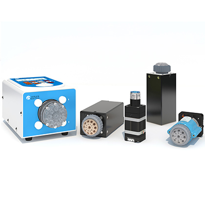
Syringe pump PLC communication troubleshooting often starts after the pump moves correctly but the PLC reports a missing, incomplete, or intermittent response. A documented RUNZE case attributes this pattern to a timing mismatch: the pump returned data faster than the PLC program processed the receive buffer. The case was resolved by matching the response delay to the controller, verifying the change on the serial lines, and saving the setting. That method is useful, but response delay should be adjusted only after wiring, protocol, baud rate, framing, addressing, and PLC receive logic have been checked.
When a RUNZE syringe pump executes a command but the PLC misses the return code, first capture the command and response timing and confirm the electrical and protocol settings. Adjust the PLC receive timeout or scan logic when possible. If the controller cannot be changed, the documented RUNZE protocol workflow uses command 0x16 to set a response delay. In the source example, parameter 0x14 represented 20 ms. The team then looped status query 0x4A, observed RS485 A and B with an oscilloscope, and used factory command 0xFC to save the setting. Do not copy 20 ms into every project. Measure the PLC requirement and verify the exact device manual and firmware.
Use an evidence-first workflow. Record one failing transaction, identify whether the motion command executed, and determine whether the problem is no transmission, no device response, a response that arrives too early, a corrupted frame, or a PLC program that reads the wrong buffer state. Those symptoms can look similar at the HMI but require different corrections.
Observed symptom | Likely area | First verification |
No pump motion and no response | Power, wiring, address, protocol, or command frame | Check supply, reference ground, bus polarity, termination, address, and a known-valid command |
Pump moves but PLC shows no response | Receive timing, timeout, buffer handling, or response delay | Capture transmit and receive timing with a protocol trace or oscilloscope |
Intermittent missing response | Scan-cycle race, short receive window, bus contention, noise, or retry overlap | Log timestamps and raw frames over many cycles |
Corrupted or unexpected bytes | Baud, parity, framing, protocol mode, grounding, or noise | Compare both endpoints and inspect the raw frame |
Works after power cycle but setting later changes | Configuration was not saved or startup code overwrites it | Read back the setting and review startup initialization |
A PLC communication task competes with the main scan, motion logic, HMI updates, alarms, and other serial devices. If the program enables receive processing after transmitting a command, a very short pump response can arrive before the logic is ready. A driver may buffer the bytes, but a program that clears the buffer, checks too late, expects a longer silent interval, or uses a narrow timeout can still report no response. The documented case describes this as a controller processing-speed mismatch and notes that the symptom appeared as a missing or absent return code even though the product performed the commanded action.
Do not assume that controller brand alone predicts the result. Scan time depends on CPU, program structure, communication module, task priority, bus loading, and firmware. The sales record mentions that some controllers processed data more slowly in the reported experience, but it does not provide a controlled benchmark across brands. Data not available in source documents. Measure the installed PLC and program rather than assigning a delay from a brand name.
Response delay cannot repair an incorrect physical link. For RS485, confirm A and B polarity, common reference where required, shielding and grounding practice, biasing and termination appropriate to the bus, and that only the intended transmitter drives the line. For RS232, confirm signal levels, transmit and receive crossover, and reference ground. For CAN, confirm CAN high and low, termination, bit rate, and node configuration. Use the applicable controlled manual for electrical limits; the reviewed case does not publish a universal wiring diagram for every pump and valve.
Next compare protocol mode, baud or bit rate, address, frame length, checksum, byte order, parity, stop bits, and command syntax. The SY-03B family catalog lists RS232 and RS485 at 9600, 19200, 38400, 57600, and 115200 bps and CAN at 100 kbps, 200 kbps, 500 kbps, and 1 Mbps. Those are product-family options, not proof that a specific unit is configured to the expected value. Query or inspect the actual configuration before changing timing.
Build a timing record from the end of the PLC request to the start of the pump response, the duration of the response frame, and the point at which the PLC receive task reads the data. Add the PLC scan time, module update time, task jitter, bus turnaround, and any software polling interval. The receive window must cover the earliest and latest valid response with margin, while the retry timeout must be long enough to avoid transmitting a second command over a delayed first response.
Use a scope or logic analyzer at the physical interface and a serial log at the software layer. A physical capture answers whether bytes were transmitted and when. A software log answers whether the PLC driver delivered them to the program and how the state machine handled them. Store timestamps, command bytes, response bytes, address, error flags, retry count, and pump state. Without both views, an early valid response can be misdiagnosed as electrical loss, and a damaged frame can be mistaken for a timeout.
The source procedure recommends adjusting the PLC side first because receive timing and timeout behavior belong to the controller application. Identify the PLC model and current response or scan requirement, then enlarge the receive window or reorganize the state machine if the platform allows it. This keeps the pump at its normal behavior and avoids applying a device-side delay that may lengthen every transaction.
When the PLC cannot be adjusted, the documented device-side method requires RUNZE protocol mode. The case states that an ASCII-controlled product must first be switched to RUNZE protocol to change response time. Under RUNZE protocol, command 0x16 sets the response delay. The example used parameter 0x14 for 20 ms because the target PLC required 20 ms. Treat this as an example of encoding and verification, not a recommended default.
· Confirm the exact product, firmware, current protocol, address, and a controlled manual that defines 0x16 for that device.
· Measure the controller requirement and choose a delay that leaves receive margin without unnecessarily extending the cycle.
· Send the response-delay command once and record the complete request and acknowledgement.
· Loop status query 0x4A and observe the response interval on the serial lines, as the source case did on RS485 A and B.
· Compare the measured interval with the intended value and repeat enough cycles to detect jitter or intermittent loss.
· After successful verification, use the applicable save procedure. The source case used factory command 0xFC to save the value as a factory setting.
The reviewed sources do not state the complete allowable delay range, resolution, command frame, checksum, acknowledgement format, firmware compatibility, or whether every current product uses identical command semantics. Data not available in source documents. Do not publish or implement a raw frame from an incomplete description. Obtain the manual for the exact product and verify commands on a non-production unit before changing deployed equipment.
A reliable PLC routine should have explicit idle, transmit, wait-for-response, validate, complete, retry, and fault states. Start the timeout when the request is actually transmitted, not when an HMI bit changes. Accept a response only when the address, command, length, and integrity check match the outstanding request. Clear the expected transaction deliberately, not by emptying the receive buffer every scan. Limit retries and prevent a late response from being interpreted as the answer to a newer command.
Separate communication success from motion completion. A valid acknowledgement may mean that the command was accepted, while a later status query confirms the mechanical state. The source procedure uses 0x4A to query current status after changing timing. Equipment logic should define what status is required before opening another valve, dispensing another reagent, or declaring a completed cycle. This distinction also makes troubleshooting easier because the log shows whether a failure occurred at transmission, acknowledgement, or motion completion.
Test | Pass evidence | Reason |
Single command capture | One valid request and one valid response at the expected interval | Confirms basic timing and frame integrity |
Repeated status queries | No missing or duplicate responses across the planned sample size | Detects intermittent timing races |
Full machine cycle | No communication faults during normal valves, pumps, HMI, and alarms | Includes real PLC load and bus traffic |
Power cycle | Delay setting remains correct and communication restarts safely | Checks persistence and startup code |
Fault injection | Open line, wrong address, late response, and duplicate response enter defined fault handling | Prevents silent process errors |
Choose a test count that reflects the machine risk and production rate. The sources do not prescribe a universal cycle count or acceptance threshold. Data not available in source documents. For a dosing instrument, record both communication results and the fluidic consequence of a missed transaction. A retry that is harmless during a status query could duplicate a dispense if the command is not idempotent.
The command may reach the pump and execute, while the return data arrives before the PLC receive logic is ready or is mishandled in the buffer. Capture both the physical response and the PLC software log to confirm this timing pattern.
No. Check wiring, protocol, baud rate, address, frame settings, and PLC receive logic first. The source procedure recommends adjusting the PLC side before adding device-side delay.
In the reviewed RUNZE protocol case, 0x16 sets device response delay. Confirm the exact product manual and firmware before use because the source set does not provide the complete command frame or universal compatibility statement.
No. The source example used 20 ms because that controller required it. Measure the target PLC, select the minimum reliable margin, and verify the result under full program load.
The documented procedure loops 0x4A status queries and observes the interval on RS485 A and B with an oscilloscope. A protocol trace and PLC timestamp log should be reviewed at the same time.
The source case uses factory command 0xFC after verification to save the setting. Confirm the save procedure for the exact device and then perform a power-cycle test to prove persistence.
The sales record states that the approach applies to current company syringe pump and switching-valve products that support response-time modification. Exact commands and supported ranges must still be confirmed from the controlled manual for each model.
Effective syringe pump PLC communication troubleshooting separates electrical, protocol, timing, and program-state evidence before any parameter is changed. When the pump acts but the return code is missed, measure the transaction and correct the PLC receive logic first. If the controller cannot be changed, the documented RUNZE protocol method uses 0x16 to add a measured response delay, 0x4A queries and an oscilloscope to verify the interval, and 0xFC to save the setting. Confirm every command against the exact product manual, then prove reliable operation through repeated cycles, a full-load machine test, power cycling, and fault handling.



 English
 日本語
 한국어
 français
 Deutsch
 Español
 italiano
 русский
 português
 Türkçe
 Nederland