86-025-5119 7362

RUNZE PFA flare fittings connect prepared PFA or PTFE tube ends to a tapered PFA sealing face. The flared tube and retaining nut form the tube connection without a separate bead, welding or adhesive. Options cover 1/4, 3/8, 1/2, 3/4 and 1 inch tube OD, with straight, elbow, tee, bulkhead and male-thread configurations. Match the fitting to your tube, flare preparation and operating conditions.

RUNZE PFA flare fittings connect prepared PFA or PTFE tube ends to a tapered PFA sealing face. The flared tube and retaining nut form the tube connection without a separate bead, welding or adhesive. Options cover 1/4, 3/8, 1/2, 3/4 and 1 inch tube OD, with straight, elbow, tee, bulkhead and male-thread configurations. Match the fitting to your tube, flare preparation and operating conditions.

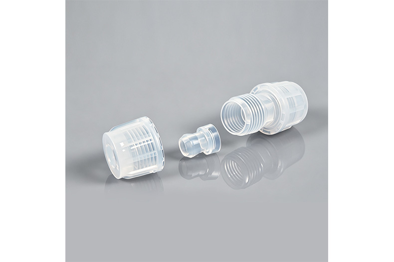
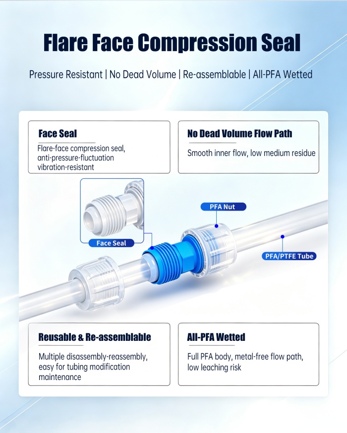
The tube end is flared before assembly and seats against the tapered face of the fitting body. Tightening the PFA nut retains the prepared tube end against this face. There is no separate bead in the flare connection.
Correct flare preparation is essential. Use the tooling and preparation procedure appropriate to the tube material, tube size and fitting model. A bead-lock tube end is not a substitute for a correctly prepared flare. The tube connection does not require welding, adhesive or an elastomer O-ring.
Item | Specification |
Product series | RZ-Y series |
Fitting material | PFA |
Compatible tube materials | PFA and PTFE; confirm suitability for the selected model |
Tube OD options | 1/4, 3/8, 1/2, 3/4 and 1 inch |
Connection method | Flared tube-to-face connection |
Published temperature range | −40°C to 200°C; application and pressure limits must be checked |
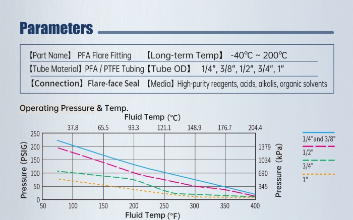
Working pressure | Size- and temperature-dependent; refer to the supplied pressure curve |
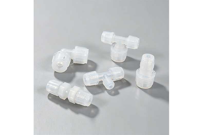
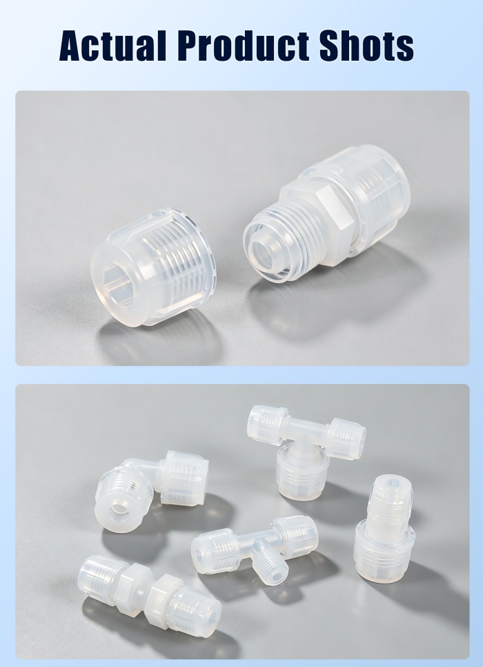
Shapes | Straight, elbow, tee, bulkhead and male-thread variants; model-dependent |
Select the pressure-temperature curve for the actual tube size. The flare-fitting chart separates the 1/4 and 3/8 inch sizes from the larger sizes, so one curve must not be applied to the whole range. Review the intended working point with RUNZE, including the fluid and any changes in temperature during operation.
Nominal tube OD | Exact inch-to-mm conversion |
1/4 in | 6.35 mm |
3/8 in | 9.525 mm |
1/2 in | 12.7 mm |
3/4 in | 19.05 mm |
1 in | 25.4 mm |
These metric values are conversions of the inch sizes, not alternative nominal metric tube sizes. For example, 1/4 inch tubing is 6.35 mm OD; it must not be substituted with 6 mm tubing without a separately specified fitting. Tube OD is the selection dimension, not tube inside diameter.
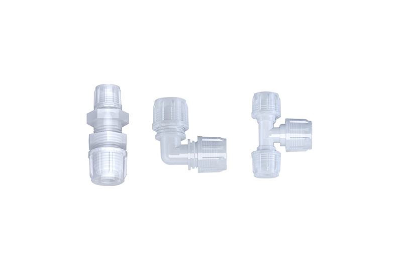
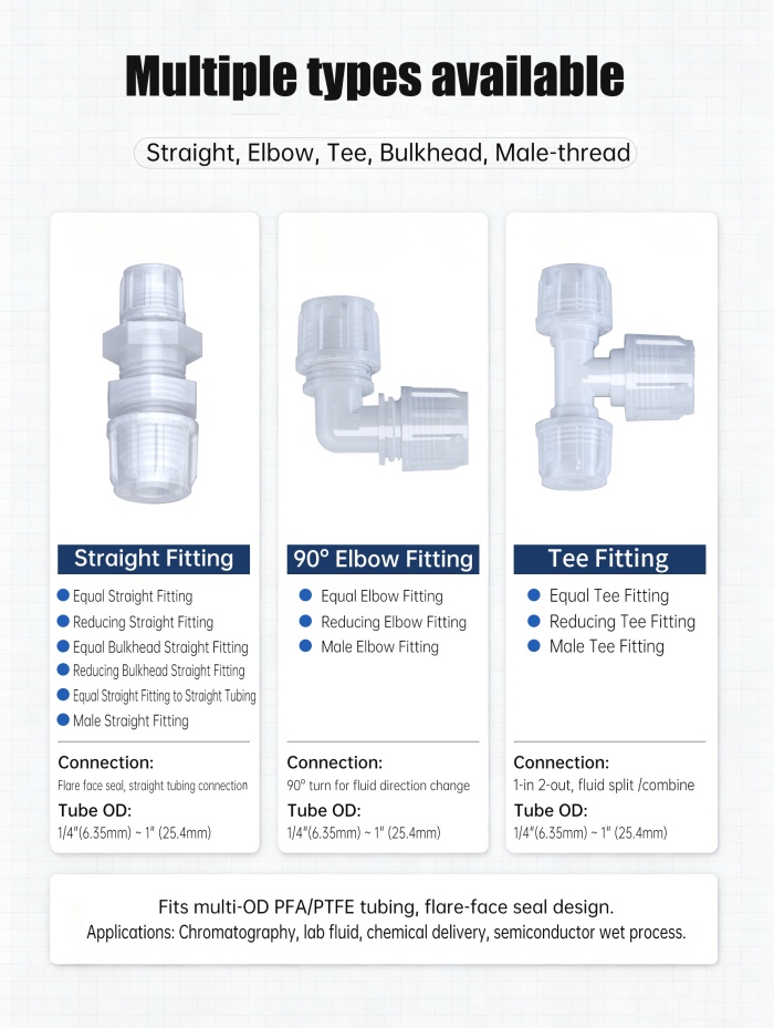
Plan the flare connection around the fluid-line layout: straight unions join tube runs, elbows change direction and tees provide branches. Select equal or reducing connections as needed and state the tube OD at every port. The chosen model must support the complete size combination, not only the largest tube in the assembly.
Configuration | Selection guidance |
Straight union | Connect tubing in a straight line; equal and reducing versions. |
Elbow | Change tube direction; select the size of each connection. |
Tee | Create a branch; confirm all three tube sizes and the branch arrangement. |
Bulkhead union | Route a tube connection through a panel; confirm mounting dimensions. |
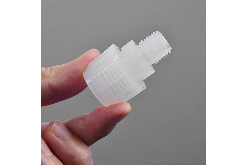
Male-thread adapter | Connect tubing to a threaded port; confirm thread standard and size. |
The RZ-Y series identifies the flare connection family. For example, RZ-Y-H-1/4-A denotes an equal straight connection for 1/4 inch tubing in the catalogue’s A material option. A and C identify the catalogue’s imported and domestic material options respectively. Confirm the full model code and material option in the quotation.
A flare-to-thread adapter combines two different interfaces: a flare connection for the tube and a male thread for the equipment port. Specify both interfaces when ordering. Include the equipment thread designation or a port drawing so the thread is not inferred from the tube size.
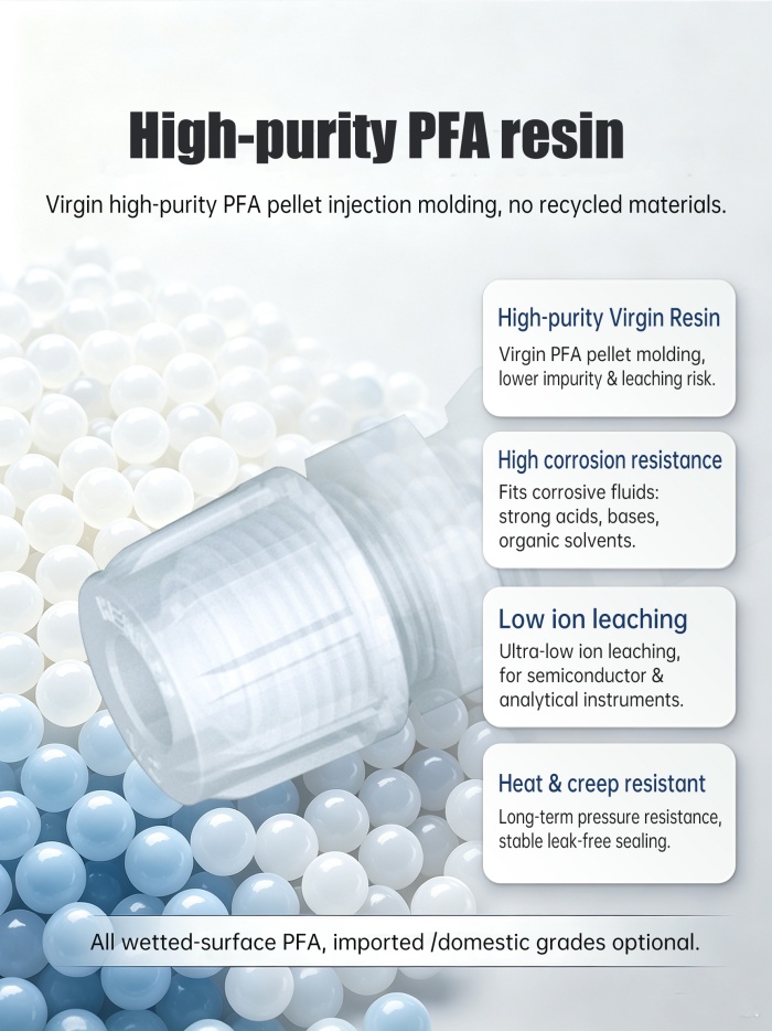
The PFA body and nut retain the flared tube against a PFA sealing face. With no separate bead at this connection, the tube preparation and face condition are central to the assembly. The supplied material data describes virgin PFA and non-metallic wetted fitting surfaces.
Chemical suitability depends on the actual medium, concentration, temperature and exposure conditions. Review all wetted components in the system, including tubing and any connected equipment. The fitting is not a blanket compatibility guarantee for every chemical or process.
Consider PFA flare tube fittings where the instrument or process line specifies a prepared flare interface. Application examples include semiconductor chemical delivery, ultrapure-water lines and analytical fluid handling. The supplied application images also cover pharmaceutical, fine-chemical, photovoltaic and battery-process equipment.
For an existing installation, match the flare family, tubing and connection dimensions before ordering a replacement. For a new system, plan the flare preparation workflow as well as the fitting layout. Confirm any process-purity or cleaning requirements separately; application examples do not establish certification.

Check that the tube and fitting match in size and connection family. Keep tube ends and sealing surfaces clean, and inspect them for damage before assembly.
For flare assembly, prepare the tube end using the specified flaring procedure and tooling. Inspect the flare for damage or uneven preparation before seating it on the fitting face and securing the nut.
No universal tightening torque is specified in this page. Use the instructions for the selected fitting, leak-test the assembled system under controlled conditions, and depressurize it before disconnection. Replace worn or damaged sealing components instead of relying on repeated tightening.
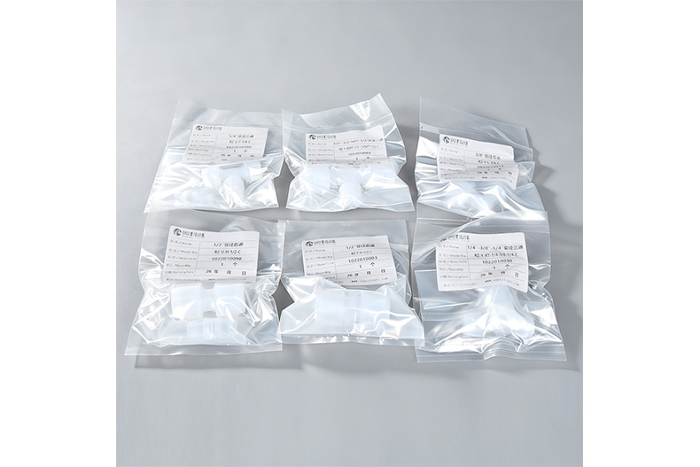
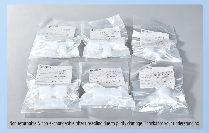
Packaging examples below show fittings from the PFA range. Labels include different connection series and should not be used to identify the model from photographs alone. The model, size, material option, quantity and packaging requirements must match the confirmed quotation.
A bead-lock connection uses a separate bead with a flat-cut tube end. A flare connection uses a prepared flared tube end against a tapered fitting face. The assembly methods and connection components are different; they are not interchangeable simply because the tube OD matches.
Yes. This connection uses a prepared flared tube end. Confirm the appropriate tool and preparation procedure for the selected PFA or PTFE tube. A flat-cut tube end alone does not provide the intended flare-to-face interface.
No. The supplied chart provides size-dependent pressure curves, and the allowable pressure changes with temperature. Identify the actual size and operating temperature before selecting a working pressure.
Reuse depends on the condition of the flare and the fitting face. Inspect both before reassembly and follow the specified preparation and assembly procedure. A damaged or distorted tube end should not be treated as a serviceable flare.
Provide the flare fitting shape, tube material and OD, any reducing combination, and the required thread or panel interface. Include the fluid, concentration, temperature, pressure, quantity and material option. Tell RUNZE whether you already have flare-preparation tooling or need the preparation requirements for a new installation.
Contact RUNZE with your tube specification and operating conditions. We can review the required flare configuration and quote the matching model. Please confirm the final connection dimensions and system compatibility before purchase.


 English
 日本語
日本語 한국어
한국어 français
 Deutsch
 Español
 italiano
 русский
 português
 Türkçe
 Nederland