
86-025-5119 7362

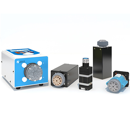
PS-10 cross contamination control is based on separating samples and reagents from the plunger pump with a storage loop, routing segmented liquids through a multiport valve, and washing the path between reactions. The RUNZE catalog describes PS-10 as a sequential-injection platform for COD monitoring and lists a driver, SV-08 multiport switching valve, RP-01 plunger pump, optional liquid detector, storage loop, reagent-distribution solenoid valve, and colorimetric assembly. This architecture can reduce direct exposure of the pump to process chemicals, but carryover control still depends on the programmed sequence, volumes, valve routing, cleaning liquid, and actual sample matrix.
The local PS-10 application case records a COD workflow in which the system loads a configuration, positions the valve, pre-fills the path, aspirates defined liquid segments, mixes them in the reaction cell, drains the reacted liquid, and washes the lines. It concludes that the programmed process prevented mutual contamination among reagents and between reagents and water in that test. That result supports the design concept, but it should not be generalized to every analyzer without a carryover study using the final tubing, reagents, samples, and method limits.
Use PS-10 as a candidate fluid-path platform when a COD analyzer needs sequential sample and reagent handling, six to sixteen valve positions, a storage loop that keeps process liquids out of the RP-01 pump chamber, programmed washing, and integrated control of the pump and SV-08 valve. The catalog states that reagent consumption can be about one twentieth of conventional chemical methods in the described sequential-injection application. Treat that as a published system-level reference, not a guaranteed saving for every method. Before release, validate blank response, sample-to-sample carryover, reagent-to-reagent carryover, recovery, cleaning volume, cycle time, and fault recovery.
The catalog diagram places pure water at the pump side of the storage loop and locates the multiport valve between the loop and the reagent, sample, pretreatment-water, air, and waste connections. The pump first moves water and uses the storage loop as a hydraulic buffer. By reversing the pump and switching ports in sequence, the system draws sample and reagent segments into the downstream path without drawing them into the pump chamber. The assembled liquid segments are then transferred toward the colorimetric reaction vessel.
Air can be introduced through a dedicated route to separate liquid segments and support bubble mixing. The catalog also describes bubble agitation in the reaction cell, followed by cooling, discharge, and line washing. Each step affects carryover. Too little water may leave residual material; too much water can dilute the next segment or increase cycle time and waste. Air gaps can improve segmentation, but gas compressibility and bubble position can alter delivered volume. The sequence must therefore be tuned and verified as one method rather than as independent component commands.
Component | Published role | Qualification focus |
RP-01 plunger pump | Moves water to aspirate and discharge liquid segments through the storage loop | Delivered volume, pressure margin, leakage, and calibration |
SV-08 multiport valve | Routes sample, reagents, air, water, reaction vessel, and waste paths | Port map, switching sequence, internal volume, sealing, and compatibility |
Storage loop | Separates sample and reagent from direct contact with the pump chamber | Capacity, residual volume, adsorption, bubbles, and cleaning |
Liquid detector option | Uses indicator color change to judge whether liquid is present | Sensitivity, liquid color, bubbles, fouling, and false detection |
Driver and configuration | Coordinates pump, valve, encoder, and communication functions | Version control, command recovery, addresses, and safe fault behavior |
Reaction and colorimetric assembly | Receives mixed liquid for reaction and optical measurement | Mixing, temperature, optical blank, recovery, and waste handling |
The catalog places PS-10 in COD monitoring for environmental discharge, municipal wastewater, industrial wastewater, and industrial process water. It cites methods associated with GB 11914-89, HJ/T 377-2007, and JJG 1012-2006. These references identify the intended application context in the source; they do not prove that a finished analyzer automatically conforms to current regulatory or metrology requirements. The instrument manufacturer remains responsible for method selection, validation, calibration, quality control, and any required certification.
The catalog states that the sequential-injection approach uses about one twentieth of the reagent consumed by conventional chemical methods. That comparison is useful for estimating development potential, but the source does not publish the baseline instrument, reagent recipe, sample volume, detection range, or uncertainty for the ratio. Data not available in source documents. For a business case, record actual reagent use per reported result on the proposed method and include standards, blanks, repeats, cleaning, and failed runs.
The application case provides stronger process evidence than a general claim because it documents three communication modes used in testing, a configuration-editor workflow, defined valve movements, separate liquid segments, mixing, discharge, and repeated water washing. It reports that the tested procedure achieved the expected prevention of mutual contamination. The case does not provide a numerical carryover percentage, detection limit, sample count, uncertainty, or long-term field duration. Use it as a workflow reference and create measurable acceptance criteria for the product under development.
Design question | PS-10 storage-loop path | Direct-contact syringe path |
Pump exposure | Sample and reagent are intended to remain outside the pump chamber | Process liquid enters the syringe or pump chamber |
Routing | SV-08 supports six to sixteen valve positions in the catalog description | Additional valves or manifolds may be required for many liquids |
Carryover control | Segment sequence plus water washing and air routing | Depends on chamber, valve, and tube flushing |
Method development | Requires coordinated configuration of pump, valve, loop, detector, reaction cell, and waste | Can be simpler for a small number of liquids |
Verification | Blank, carryover, recovery, cleaning, and fault-sequence tests are still required | The same analytical checks remain required |
The comparison explains fluid-path structure rather than proving that one architecture is always cleaner or cheaper. A simple one-liquid analyzer may not benefit from PS-10 complexity. A multi-reagent COD method can benefit from coordinated routing and pump isolation, but only when the configured process meets analytical acceptance criteria and the team can support the controls, cleaning, and maintenance workflow.
Start with a complete port map. List every sample, reagent, dilution or pretreatment water, air source, reaction vessel, rinse source, and waste destination. The catalog describes six to sixteen valve positions and its ordering table shows ten-port and twelve-port SV-08 configurations. Do not reserve every position for routine liquids. Service flushing, calibration standards, blanks, and future method changes may require additional routes. Confirm the exact valve head, port count, wetted materials, and model code in the current drawing and quotation.
Size the storage loop from the largest planned segment train, not from a single reagent dose. It must accommodate the sequence while maintaining the intended separation from the pump chamber. Too little loop volume risks moving process liquid toward the pump; excessive volume can increase residence time, internal surface area, purge demand, and bubble retention. The source documents do not publish standard loop capacities or a universal sizing equation. Data not available in source documents. Build a volume budget from tubing inner diameter, length, valve cavities, connectors, detector cell, and safety margin.
The catalog ordering table lists FEP tubing and 1/4-28 UNF connection options associated with the system page. Final tubing diameter affects pressure loss, dispersion, segment length, and wash volume. Smaller tubing can reduce internal volume but increase restriction and sensitivity to particles. Larger tubing can reduce restriction but require more liquid for a given line length. Select tubing, fittings, and valve ports as one fluid path and verify them with the real sample matrix.
The application case uses Config Editor V1.0.0 to load a PS-10 configuration and run a predefined sequence. It describes reset, liquid pre-fill, path selection, reagent and sample aspiration, transfer to the reaction vessel, mixing, discharge to waste, and water washing. Configuration files should be revision controlled with the analyzer software because a timing or port-number change can alter delivered composition or contaminate the next result even when all hardware remains functional.
Define fault behavior for power loss, communication interruption, an unexpected detector state, a blocked waste line, a valve-position error, or an incomplete pump stroke. A safe recovery should know which liquid may be in each segment before it decides whether to resume, drain, or wash. The catalog driver drawing labels RS485 and CAN connections and separate motor and encoder ports. Protocol details, command timeouts, error codes, and restart state are data not available in source documents and must be confirmed from the applicable control manual.
Cleaning validation should challenge the most difficult transition, not only water after water. Use a high-concentration sample or reagent followed by a blank, then measure the residual against a predefined limit. Repeat the test across the expected sample matrix, temperature, tubing age, and idle time. Record the wash volume and cycle time required to pass. A visual absence of color or a stable detector signal is not a substitute for analytical carryover data when the method limit is low.
1. Create a port map for every sample, reagent, water, air, reaction, drain, and service route.
2. Build a volume budget for the storage loop, valve, tubing, fittings, detector, and reaction vessel.
3. Define the exact aspiration, air-gap, mixing, discharge, and wash sequence in a controlled configuration file.
4. Measure delivered volumes and confirm that process liquid does not reach the pump chamber in normal and fault cases.
5. Run blank, carryover, recovery, repeatability, and cleaning tests with challenging real matrices.
6. Test power interruption, communication loss, valve error, blocked waste, detector error, and safe restart logic.
7. Measure actual reagent consumption and cycle time rather than assuming the published one-twentieth reference applies unchanged.
No. The storage-loop and washing architecture is designed to control carryover, and the local application case reports success in its tested procedure. A finished analyzer still needs numerical carryover and blank validation with the final method.
The catalog describes a single valve body with six to sixteen positions and shows ten-port and twelve-port SV-08 configurations in the ordering table. Confirm the exact valve head and model code before ordering.
The published architecture uses a storage loop so sample and reagent do not directly contact the RP-01 pump chamber during the intended sequence. The loop volume and fault handling must be designed to preserve that separation.
The catalog gives one twentieth as a reference for the described sequential-injection application. The baseline, recipe, and uncertainty are not published, so actual consumption must be measured for the proposed analyzer method.
The catalog lists a driver, SV-08 multiport valve, RP-01 plunger pump, optional liquid detector, storage loop, reagent-distribution solenoid valve, and colorimetric assembly. Confirm the supplied scope for the ordered configuration.
Challenge a difficult high-concentration sample or reagent followed by a blank. Measure the residual against a defined analytical limit and repeat across expected matrices, tubing age, temperature, wash volume, and idle time.
The driver diagram shows RS485 and CAN connections plus motor and encoder ports. The applicable manual should be checked for protocol, timing, fault codes, addressing, and restart behavior.
PS-10 cross contamination control gives COD analyzer designers a structured way to isolate the plunger pump, route multiple liquids, create sequential segments, mix in a reaction cell, drain waste, and wash the path. Its value depends on disciplined system design: select enough valve positions, size the storage loop from the full segment train, control configuration revisions, and validate carryover with measurable blanks and recovery tests. The published one-twentieth reagent reference and the local application result are useful evidence for prototype planning, but production approval should rest on the final analyzer method and real sample matrix.


 English
 日本語
 한국어
 français
 Deutsch
 Español
 italiano
 русский
 português
 Türkçe
 Nederland