
86-025-5119 7362

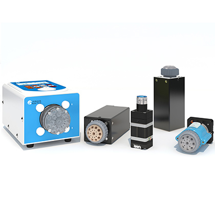
The SV07M switching valve is a multiport rotary valve platform for equipment designers who must route one fluid path among multiple ports and need more torque or a larger-bore option than a compact valve can provide. A documented prototype inquiry asked for ten channels and a 2.0 mm bore for transferring larger liquid volumes. The current pump-and-valve catalog identifies an SV07M large-bore TC20QP head with 6, 8, 10, or 12 channels at a 2.0 mm default bore, which makes that configuration a technically aligned candidate. Bore size alone does not establish flow, however; the application still requires actual flow, viscosity, pressure, tubing, fitting, dead-volume, and chemical-compatibility data.
This guide separates the standard and large-bore head families, shows the published tradeoffs between channel count and internal volume, and defines the questions that should be answered before a prototype order. It excludes price figures from the sales record because pricing is time-sensitive and not a technical specification.
For a ten-port, 2.0 mm fluid path, screen the SV07M with a TC20QP ten-channel head. The catalog lists 2.0 mm for TC20QP heads with 6, 8, 10, or 12 channels, 1/4-28 UNF interfaces, 34.7 microliters of adapter cavity volume, and 106.8 microliters of port-plus-adapter volume. Verify whether the 2.0 mm bore is a hard mechanical requirement or only a proxy for desired flow. The source documents do not provide a flow-rate curve, pressure-drop curve, fluid-specific compatibility table, or service-life result for the proposed application, so prototype testing is required.
Start with the switching topology. Specify the number of destinations, whether one common port connects to one selected port at a time, and whether any ports must be blocked or isolated in a defined state. A ten-channel requirement is not interchangeable with ten total physical connections unless the common port and naming convention are understood. The current selection table offers standard SV07M heads in 6, 8, 10, 12, 16, 24, and 28-channel versions, while large-bore TC20QP heads cover 6, 8, 10, 12, and 16 channels. TC20QSP covers 6 and 8 channels with a still larger bore.
Next identify the reason for the bore requirement. A larger bore can reduce restriction, but system flow also depends on the narrowest fitting, tube inner diameter, liquid viscosity, upstream pressure, downstream resistance, and required switching time. If the customer's objective is simply to reach a target transfer time, engineering should size the entire fluid path from the required flow and acceptable pressure drop. If a 2.0 mm passage is a fixed requirement because of particles, cleaning, or an existing manifold, record that constraint explicitly and keep it through the prototype review.
Head family | Published channel and bore options | Published internal volumes | Selection use |
Standard SV07M | 6/8/10/12 channels: 1.2 mm; 16: 1.0 mm; 24/28: 0.6 mm | 6/8/10: 5 microliters adapter, 27.5 microliters combined; 12: 5/30.9; 16: 3.1/19.8; 24: 1.55/7.8; 28: 1.55/8.32 | Lower internal volume where the standard bore supports the required fluid path |
TC20QP large bore | 6/8/10/12 channels: 2.0 mm; 16: 1.5 mm | 6/8/10/12: 34.7 microliters adapter, 106.8 microliters combined; 16: 20.1/61.1 | Larger passage for higher-throughput or lower-restriction requirements, subject to testing |
TC20QSP large bore | 6/8 channels: 3.0 mm | 92.6 microliters adapter, 254 microliters combined | Largest listed bore when six or eight channels are sufficient and larger internal volume is acceptable |
The table exposes an important design tradeoff: larger passages can bring substantially larger internal volumes. In a flushing process that may increase purge demand, carryover risk, and waste. In a bulk-transfer process it may be acceptable. The correct head is therefore not automatically the one with the largest bore.
For the listed SV07M head families, the catalog states a normal pressure range of 0 to 0.6 MPa and a water-test pressure range of 0 to 1.0 MPa. The water-test figure is not a continuous operating rating for every liquid, temperature, fitting, or switching condition. Use 0.6 MPa as the published normal range and verify transient pressure, pump shutoff pressure, blocked-line scenarios, and the ratings of every connected tube and fitting. The catalog lists a maximum liquid temperature of 100 degrees C for the valve head, but the complete assembly and process compatibility still require confirmation.
The catalog describes ceramic wetted components for the listed heads. Ceramic resistance does not establish compatibility for the entire fluid path, because tubing, fittings, seals, adhesives, and any adapter materials can become the limiting components. Chemical compatibility for a specific solvent, slurry, buffer, cleaning solution, or concentration is data not available in source documents. Provide the full medium list and cleaning procedure for technical review and test the final wetted assembly.
Internal volume affects how much liquid remains in the valve and adapters when the route changes. For a 10-channel standard head, the catalog groups the configuration with 5 microliters of adapter cavity volume and 27.5 microliters of combined port-and-adapter volume. The 10-channel TC20QP group is much larger at 34.7 and 106.8 microliters. These values should be included in a system-level purge calculation together with tube and fitting volumes.
Do not treat the internal volume as the exact carryover of a real process. Mixing, wetting, diffusion, surface condition, flow direction, and the selected flush volume all matter. If cross-contamination is critical, define an analytical carryover limit, switch through the planned sequence, flush with the intended protocol, and measure the residual. The source documents do not give a universal purge multiplier or validated carryover result.
SV07M lists RS232 and RS485 interfaces, with 9,600, 19,200, 38,400, 57,600, and 115,200 bps options. The catalog names a custom protocol, ASCII, and Modbus, and notes that CAN can be customized. It also lists automatic initial-position detection through the motor channel as an option. Before integration, confirm the exact ordered communication variant, address behavior, initialization sequence, response handling, and the safe state after a power interruption. A protocol name alone is not enough to prove compatibility with an existing host controller.
The listed full-rotation switching time is 4 seconds for one valve-head revolution, and the published power input is DC 24 V at 3 A with 60 W consumption. These values help size the electrical supply and estimate worst-case route-change timing. The actual command-to-fluid timing also includes host latency, acceleration behavior, port distance, fluid compliance, and any confirmation logic in the equipment.
1. Confirm the common-port routing logic, destination count, and required fail-safe position.
2. State the real target flow, transfer volume, maximum allowable pressure drop, and cycle time.
3. List viscosity, temperature, particles, solvent composition, cleaning agents, and concentration ranges.
4. Decide whether 2.0 mm is a fixed passage requirement or a method for meeting the flow target.
5. Calculate system internal volume using the valve, adapters, fittings, and tubing, then define a purge target.
6. Confirm the ordered protocol and electrical interface with the host-control design.
7. Test flow, pressure, leakage, switching accuracy, carryover, cleaning, and endurance on the complete prototype fluid path.
The catalog lists the TC20QP large-bore head in 6, 8, 10, and 12-channel versions with a default 2.0 mm bore. The corresponding ten-channel selection code should be confirmed against the current quotation and drawing.
No. Flow depends on the complete path, pressure source, viscosity, tubing, fittings, and downstream resistance. A flow curve for the proposed application is data not available in source documents.
The catalog lists 0 to 0.6 MPa as the normal pressure range and 0 to 1.0 MPa as a water-test range. The water-test value should not be used as a universal continuous operating rating.
For the 6/8/10/12-channel TC20QP group, the catalog lists 34.7 microliters of adapter cavity volume and 106.8 microliters of combined volume, versus 5 and 27.5 microliters for the standard 6/8/10-channel group.
RS232 and RS485 are listed, with several baud-rate options. The catalog names custom, ASCII, and Modbus protocols and notes that CAN can be customized. Confirm the exact ordered firmware and wiring.
The catalog identifies ceramic wetted components, but compatibility of the complete path depends on every wetted material and operating condition. Fluid-specific compatibility is data not available in source documents.
Validate route mapping, pressure, leakage, actual flow, switching timing, carryover, purge volume, cleaning effectiveness, command recovery, and cycle endurance with the final tubing, fittings, fluid, and control software.
The SV07M switching valve is a technically aligned option for a ten-channel, 2.0 mm prototype when it is paired with the TC20QP large-bore head. The choice should still be justified by the complete fluid path: required flow, pressure, internal volume, purge demand, fluid compatibility, interfaces, and switching sequence. Use the published dimensions and ratings for screening, then verify the assembled system under real media and duty conditions before approving a production configuration.



 English
 日本語
 한국어
 français
 Deutsch
 Español
 italiano
 русский
 português
 Türkçe
 Nederland