
86-025-5119 7362

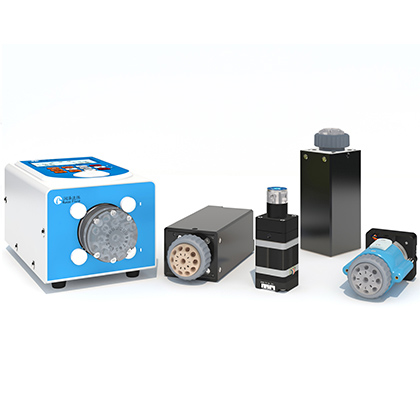
A microliter plunger pump is often selected late in an analyzer program, after the assay volume, enclosure, and controller architecture are already constrained. That sequence creates avoidable risk. Capacity alone does not determine whether a pump will integrate cleanly: screw lead affects commanded travel, the flow path sets chemical-compatibility questions, pressure limits must be interpreted under their stated test condition, and service access determines whether deposits can be managed without removing the complete fluid module. This guide translates the available RUNZE RP42 source documents into a practical OEM review. It also distinguishes catalog-confirmed specifications from claims that still need an application-specific report or sample test.
Quick answer: Start with the required dispense range, then choose the 100, 500, or 1000 uL RP42 capacity and decide whether the 0.635 mm or 1.27 mm screw lead better fits the required motion resolution and cycle time. Confirm the 1/4-28 UNF fluid ports, wetted materials, pressure references, upright service space, and whether the integrated-drive or no-drive configuration matches the controller design. Treat accuracy, repeatability, chemical compatibility, and life as application-level verification items, even when a source document provides a nominal value.
The RUNZE pump and valve catalog identifies the RP42 as a compact industrial plunger pump for environmental equipment, medical analytical equipment, and non-standard precision sampling instruments. The catalog lists a 12.7 mm rated stroke, a 7.08 mm plunger diameter, a maximum speed of 300 rpm, an L-shaped two-port pump head, and three nominal capacities: 100, 500, and 1000 uL. Selection codes are available with and without an integrated drive. These details support early mechanical and controller planning, but the exact ordering code still has to be checked against the desired capacity, screw lead, and drive configuration.
The same catalog lists PCTG, FKM, UPE, and alumina ceramic as wetted materials. It shows 1/4-28 UNF female inlet/outlet ports and two 10-32 UNF cleaning ports around the ceramic plunger. The listed operating environment is 5 to 55 degrees C and less than 80% RH without condensation. Catalog dimensions are 44.3 x 62.34 x 134.4 mm and mass is 0.4 kg. Use the current controlled drawing, rather than a blog image or rounded sales dimension, for enclosure release.
1. Define the smallest and largest commanded liquid volumes, including prime, wash, sample, reagent, and waste-transfer steps. A capacity that is attractive for the smallest dose may require multiple strokes for larger transfers.
2. Translate the assay cycle into stroke-time requirements. The catalog gives different linear-speed and rated-stroke-time ranges for the two screw leads, so lead selection must be reviewed with the control profile rather than treated as a mechanical detail.
3. Check the pressure condition at the pump, not only at the final outlet. Tubing length, fittings, restrictions, filters, valve paths, liquid viscosity, and acceleration can all change the instantaneous load.
4. Review every wetted material against the actual reagent, concentration, temperature, exposure duration, cleaning agent, and storage condition. A material list is not a chemical-compatibility guarantee.
5. Choose the electrical integration boundary. The catalog offers versions with and without a drive; the sales-experience file describes integrated-drive and external-drive approaches. Obtain the applicable interface and protocol document for the exact ordering code before freezing the PCB and harness.
6. Plan upright installation and cleaning access. The catalog recommends upright installation for easier inspection, maintenance, and cleaning and to reduce avoidable piping resistance and pressure loss.
Screw lead changes the relationship between motor rotation and linear plunger motion. The catalog pairs the 0.635 mm lead with 4000 control steps and a listed linear-speed range of 0.01 to 3.175 mm/s. The 1.27 mm lead uses 2000 control steps and a listed range of 0.02 to 6.35 mm/s. At the rated stroke, the corresponding catalog time ranges are 4 to 1200 seconds and 2 to 600 seconds. Those values describe commanded mechanics; they do not, by themselves, establish delivered-volume accuracy under a particular fluid load.
Selection factor | 0.635 mm lead | 1.27 mm lead |
Control steps | 4000 | 2000 |
Listed linear speed | 0.01-3.175 mm/s | 0.02-6.35 mm/s |
Rated-stroke time | 4 s at 300 rpm to 1200 s at 1 rpm | 2 s at 300 rpm to 600 s at 1 rpm |
Engineering implication | Finer commanded travel per motor revolution; verify cycle time | Higher commanded travel per revolution; verify low-volume needs |
Do not convert these mechanics into an unsupported minimum dispense volume. The sales-experience file states a minimum dispensing resolution of 0.025 uL, volume error of no more than 1%, and repeatability of 0.3% to 0.7% at rated stroke. The available catalog page does not reproduce the accuracy test method, liquid, sample count, or acceptance calculation. Request the applicable accuracy report and reproduce the intended liquid-handling sequence before using those figures as an instrument-level guarantee.
The catalog gives a positive-pressure reference of 0 to 0.5 MPa and a negative-pressure reference of 0 to 0.06 MPa, with a one-minute holding condition. These are useful screening values, not a complete duty-cycle envelope. The source documents do not provide a pressure-versus-speed curve, a viscosity derating curve, allowable pressure ripple, or a continuous high-pressure lifetime result. Data not available in source documents. If the system includes a narrow needle, membrane, long capillary, or fast valve event, measure pressure at the pump during the real motion profile.
Capacity also should not be confused with continuous flow rate. A 1000 uL chamber can move more liquid per full stroke than a 100 uL chamber, but net process throughput depends on fill time, dispense time, valve switching, acceleration, refill routing, and any purge or wash steps. For continuous delivery, the system architecture may require buffering or multiple pumping elements. The current RP42 source page does not provide a validated continuous-flow configuration. Data not available in source documents.
The confirmed wetted-material set is PCTG, FKM, UPE, and alumina ceramic. That list is the starting point for compatibility review. Compatibility must still be checked for the exact formulation because concentration, mixed solvents, temperature, dwell time, and cleaning chemistry can change swelling, permeation, stress cracking, surface deposition, or seal behavior. The sales-experience file specifically flags high-viscosity, particle-containing, and strongly crystallizing liquids as applications that require prior testing rather than an immediate recommendation.
For aqueous reagents, review salts and drying behavior, not just pH.
For organic solvents, check PCTG and FKM exposure using the actual concentration and cleaning sequence.
For suspensions, evaluate particle size, settling, valve restrictions, and ceramic/seal wear.
For crystallizing liquids, validate whether the cleaning circuit reaches all deposit-prone surfaces.
The RP42 places two 10-32 UNF cleaning interfaces beside the ceramic plunger so a cleaning circuit can reach the plunger surface. This can support a service strategy for deposits, but the source documents do not specify a universal cleaning fluid, pressure, duration, frequency, or validated removal efficiency. Data not available in source documents. The OEM should define a reagent-specific wash procedure and verify that the wash does not introduce incompatible chemistry into seals or neighboring components.
Design the enclosure so technicians can identify, connect, and inspect the cleaning ports without disturbing the main 1/4-28 UNF fluid connections. Also provide leak containment and a controlled destination for wash liquid. If cleaning requires disassembling the instrument around the pump, the nominal presence of cleaning ports will not deliver its intended maintenance advantage.
The catalog reports 3 million cycles without leakage using pure water, with one rated stroke counted as one cycle. That is a specific test statement. It does not establish 3 million cycles for every reagent, pressure, speed, orientation, cleaning schedule, or partial-stroke pattern. For reliability planning, document the expected daily strokes, liquid exposure, idle condition, pressure profile, and allowable leakage criterion, then run an accelerated or representative endurance test. A useful qualification plan separates functional volume checks, external leakage inspection, internal bypass assessment, and post-test visual examination.
Confirm 100, 500, or 1000 uL nominal capacity against the complete assay sequence.
Select 0.635 or 1.27 mm screw lead using both low-volume command needs and cycle time.
Confirm integrated-drive or no-drive ordering code and obtain its current electrical interface document.
Verify 1/4-28 UNF process connections and 10-32 UNF cleaning connections in the plumbing BOM.
Review PCTG, FKM, UPE, and alumina ceramic against every process and cleaning fluid.
Measure dynamic pressure in a representative assembly; do not rely only on a static one-minute reference.
Reserve upright mounting, connector access, leak control, and service clearance in the enclosure.
Request accuracy, repeatability, protocol, and life evidence that matches the final configuration.
The catalog lists 100, 500, and 1000 uL variants. Capacity should be selected from the full liquid-handling sequence, not from the smallest dispense alone.
The catalog contains ordering codes both with and without a drive. Confirm the exact suffix and obtain the matching interface documentation before electrical design release.
The main inlet/outlet connections are listed as 1/4-28 UNF female ports. The two cleaning interfaces are listed as 10-32 UNF.
The catalog provides a positive-pressure reference up to 0.5 MPa with a one-minute holding condition. It does not provide a continuous pressure-versus-life envelope. Data not available in source documents.
Compatibility cannot be concluded from a material list alone. Check the exact reagent and cleaner against PCTG, FKM, UPE, and alumina ceramic, then test the final sequence.
It covers a source-reported pure-water test in which one rated stroke counts as one cycle and no leakage was reported. It should not be generalized to other liquids or duty cycles without validation.
The 0.635 mm lead provides more listed control steps and lower listed linear speed; the 1.27 mm lead provides faster listed travel. Choose using required command granularity, cycle time, and application testing.
A microliter plunger pump should be selected as part of the complete fluidic and control architecture. The RP42 source documents provide a useful configuration framework: three capacities, two screw leads, drive and no-drive options, defined process and cleaning ports, a stated wetted-material set, compact dimensions, pressure references, and a qualified pure-water life statement. The remaining work is application validation. Confirm dynamic pressure, chemical exposure, delivered-volume performance, protocol behavior, service access, and endurance in the final instrument before converting catalog data into a production claim.


 English
 日本語
日本語 한국어
한국어 français
 Deutsch
 Español
 italiano
 русский
 português
 Türkçe
 Nederland