
86-025-5119 7362

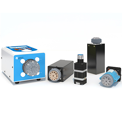
The LM80C industrial peristaltic pump is intended for engineers who need an integrated, high-flow tubing pump with local controls, several operating modes, and interfaces for automated equipment. The published catalog identifies a 1 to 500 rpm speed range, an RZ35-3H-U three-roller pump head, compatibility with 73# and 82# tubing, and a maximum reference flow of 9,616 mL/min with 82# tubing. That flow value was measured with water at normal temperature and pressure and is a reference, not a guarantee for a process fluid. Selection therefore begins with the real medium, target flow window, duty cycle, tubing material, suction conditions, and system backpressure.
A sales application record positions LM80C for automated batching, continuous feed, chemical and food raw-material transfer, and equipment integration. Those uses are reasonable starting points, but the pump should be qualified with the actual liquid. Viscosity, entrained solids, plant fibers, temperature, tube aging, and downstream restriction can all shift delivery from a water-based catalog curve. This guide turns the available specifications into a practical qualification sequence without extending them beyond the source documents.
Choose LM80C when the application needs an integrated large-flow peristaltic pump, a published water-reference capacity up to 9,616 mL/min, 73# or 82# tubing, four operating modes, and a choice of keypad, serial, foot-switch, or analog control. Do not select it from the maximum-flow number alone. Confirm the required flow at the real viscosity and pressure, verify tube compatibility and expected replacement interval through testing, and recalibrate after installing a new pump head or tube. If the process needs a water-reference ceiling above the LM80C range, the TS600 on the same catalog page has a higher published maximum reference flow, but it represents a different integration and control approach.
A defensible selection starts with the minimum and maximum process flow, not with a single nominal point. The catalog curve shows that output changes with speed, tube size, and tube material. For example, the 82# silicone-tube series reaches the highest LM80C reference value at 500 rpm, while the smaller 73# series produces less at comparable speeds. Because these values were generated with water, they should be treated as screening data for pump and tube selection. Final settings should come from a controlled test using the production fluid, intended suction lift, fittings, and discharge restriction.
The next decision is whether the process is continuous, batch-oriented, or scheduled. LM80C lists continuous, quantitative, calibration, and scheduled modes. Quantitative mode uses a configured liquid amount and run time; scheduled mode supports a sequence of wait, run, interval, and repeated run stages. The source does not provide guaranteed batch accuracy, repeatability, or minimum controllable dose for every tube and fluid. If these values are mandatory acceptance criteria, record them as data not available in source documents and define an application test before release.
LM80C and TS600 share the RZ35 family and appear together in the pump catalog, but their published limits and control descriptions differ. The table is a screening comparison only.
Criterion | LM80C | TS600 |
Published speed range | 1 to 500 rpm | Up to 900 rpm |
Maximum reference flow | 9,616 mL/min with 82# tubing | 14,283 mL/min with 82# tubing |
Pump head and tubing | RZ35-3H-U; 73# and 82# | RZ35-3H-U; 73# and 82# |
Operator and automation controls | Keypad; RS232/RS485; foot switch; analog control | Controller adjusts speed, distance, delay, and cycle count |
Named operating modes | Calibration, continuous, quantitative, scheduled | Data not available in source documents |
Published weight | 13 kg | 8.75 kg |
Selection implication | Integrated process control and recipe-oriented operation | Higher published water-reference capacity when the controller architecture fits |
Both maximum-flow figures are catalog reference data obtained with water under normal temperature and pressure. They should not be interpreted as process guarantees or as proof that one unit is more accurate than the other.
A peristaltic pump meters by repeatedly compressing flexible tubing. Tube inner diameter, wall thickness, elastic recovery, material, manufacturing tolerance, and accumulated fatigue therefore influence flow. The LM80C catalog lists 73# and 82# tubing. The corresponding nominal dimensions are 9.5 x 3.2 mm for 73# rubber, 9.6 x 3.5 mm for 73# silicone, 12.7 x 3.2 mm for 82# rubber, and 12.7 x 3.5 mm for 82# silicone. These dimensions help define the mechanical fit, but chemical compatibility must still be checked against the actual formulation.
For fluids containing fibers or light solids, the pump's separated fluid path can be attractive because the medium remains inside the tube. That does not eliminate the risk of blockage, particle settling, tube abrasion, or concentration changes. A useful qualification records inlet condition, tube material and lot, speed, actual delivered mass or volume, operating time, and the drift observed before replacement. The source documents do not provide a universal tubing life or allowable drift threshold for every medium. Those values must be established in the user's test conditions.
The catalog instructs users to calibrate on first use and after changing the pump head or tubing when accurate liquid results are required. A practical method is to run the assembled system at the intended operating point, collect liquid for a defined interval, measure it with a suitable gravimetric or volumetric method, enter the correction through calibration mode, and repeat the measurement. Use enough collection time to reduce the influence of startup transients and pulsation. The chosen method should match the process tolerance and the liquid's density behavior.
Calibration cannot remove every source of variation. Tube relaxation, temperature, backpressure, suction lift, fluid viscosity, and wear can change after the initial correction. For batch systems, verify both the individual dose and a run of repeated doses. For continuous feed, verify the average flow and its stability over the intended duty period. The source documents do not state an acceptance interval, so the maintenance team should set recalibration triggers from process risk and measured drift.
LM80C supports keypad control, RS232/RS485 communication, foot-switch input, and analog control. The catalog also lists external inputs for speed regulation, direction, and start/stop control. Before the mechanical design is frozen, the controls engineer should confirm which interface will own the pump state, how local and remote commands are interlocked, and what the host system should do after a power interruption or communication loss. Electrical integration should follow the supplied product documentation; the published power input is DC 48 V +/-10% and the listed power consumption is 144 W.
The enclosure is listed as IP31, with an operating environment of 0 to 40 degrees C and less than 80% relative humidity. Those ratings matter in washdown, dusty, or humid areas. IP31 is not a washdown rating. If the pump is installed near open ingredients or cleaning operations, the equipment designer should provide appropriate guarding, spill control, and enclosure protection rather than assuming the standard housing covers the process environment.
1. Define the liquid, viscosity range, temperature, solids or fibers, and chemical-compatibility constraints.
2. State the normal, minimum, and peak flow, plus the required batch size or continuous duty period.
3. Map suction lift, discharge backpressure, fittings, tube length, and elevation changes in the real fluid path.
4. Screen 73# and 82# tube options with the catalog curve, then test the selected material and production fluid.
5. Choose continuous, quantitative, scheduled, or externally controlled operation and define command ownership.
6. Calibrate the assembled system and measure repeatability, drift, pulsation, and tube condition over the target duty cycle.
7. Document tube-replacement and recalibration triggers before production release.
The catalog lists a maximum reference flow of 9,616 mL/min with 82# tubing. It was obtained with water at normal temperature and pressure, so actual process flow must be verified with the intended medium and system resistance.
The catalog lists 73# and 82# tubing, with rubber and silicone reference curves. Chemical compatibility and service life for a specific formulation are data not available in source documents and require application testing.
The published control options include RS232/RS485 communication and analog control, along with start/stop, direction, and speed-related external inputs. The exact host command implementation should be confirmed from the current product manual.
The catalog calls for calibration at first use and after changing the pump head or tubing when accurate liquid results are needed. Additional intervals should be set from measured drift and process risk.
Yes. The catalog lists quantitative and scheduled modes in addition to continuous and calibration modes. Scheduled operation can use wait, run, interval, and repeated-run stages.
Potential suitability depends on the fluid, tube material, inlet condition, required flow, and restriction. The sales case notes applications involving extracts and light solids, but performance limits for a specific liquid are data not available in source documents.
Evaluate TS600 when the required water-reference capacity exceeds the LM80C range or its controller-based architecture is preferred. The catalog lists up to 14,283 mL/min with 82# tubing, but the real fluid still requires qualification.
The LM80C industrial peristaltic pump is a practical candidate for automated high-flow transfer when its integrated modes, controls, RZ35-3H-U pump head, and 73#/82# tube options match the system architecture. The correct engineering decision is based on a tested operating window, not the 9,616 mL/min water-reference ceiling alone. Qualify the actual medium, confirm tube compatibility, calibrate the assembled fluid path, and define replacement and recalibration rules before production approval.


 English
 日本語
 한국어
 français
 Deutsch
 Español
 italiano
 русский
 português
 Türkçe
 Nederland