
86-025-5119 7362


Flanged fittings are used to connect rigid tubing to flat-bottom ports in fluidic transfer systems. The tube end is mechanically flanged, then compressed by a nut and ferrule or clip structure to form a sealed connection at the receiving port. This type of connection is common in laboratory automation, analytical instruments, reagent transfer modules, water treatment equipment, and other systems that use rigid polymer tubing.
This guide explains how to use flanged fittings correctly, how to choose material and thread options, and what installation checks help reduce leakage, tube loosening, and assembly errors. The article is written for engineers, OEM designers, and maintenance teams who need a practical fitting installation reference rather than a general catalog description.
To use flanged fittings, first select the correct nut, ferrule or clip, thread type, tubing outer diameter, and wetted material for the receiving port. Flange the rigid tubing with the proper flanging tool, slide the nut and clip into position, insert the flanged tube fully into the flat-bottom port, and finger-tighten the fitting until snug. Do not force the connection or over-tighten it.
For two-end flanged tubing, slide two clips and two nuts onto the tube before forming both flanges. For one-end flanged tubing, one clip and one nut can be installed before or after the single end is flanged, depending on assembly access. After repeated use, especially in higher-pressure or frequently serviced systems, inspect the flanged tube and replace it if sealing performance changes.
A flanged fitting creates a seal by using the shaped end of the tubing as the sealing surface. The flanged tube end is pressed against the receiving port by the nut and ferrule or clip. Because the tube bore is not intentionally narrowed by a ferrule biting into the tube wall, the connection can help maintain a stable internal flow path when assembled correctly. For a conventional finger-tight connection for Teflon tubing, Runze also supplies flanged fittings for rigid fluidic assemblies.
The final sealing performance still depends on port geometry, tubing material, flange quality, tightening force, pressure, chemical compatibility, and repeated assembly conditions. For critical systems, the connection should be validated under the actual liquid, pressure, temperature, and maintenance cycle.
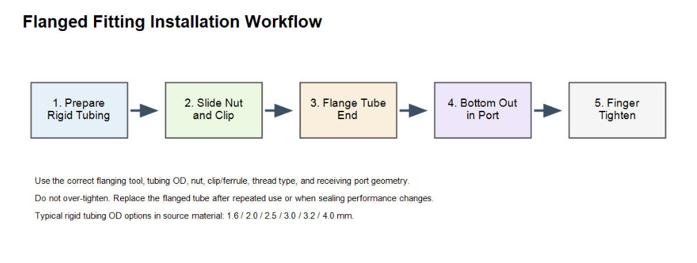
Figure 1. Typical workflow for installing a flanged fitting on rigid tubing.
The available material combinations include PEEK, PP, PVDF, PPS, PTFE, and SUS316 ferrules. When chemical resistance and repeated disassembly are important, buyers can also review Runze’s PEEK fittings for compatible fluidic assemblies.
Fitting / Material Combination | Long-term temperature range from source material |
PEEK nut with PPS ferrule | -40 to +200 C |
PEEK nut with SUS316 ferrule | -50 to +260 C |
PP nut | -20 to +90 C |
PTFE nut | -200 to +260 C |
PVDF nut with PPS or SUS316 ferrule | -40 to +150 C |
PP nut with PPS or SUS316 ferrule | -20 to +90 C |
PPS nut with PPS or SUS316 ferrule | -40 to +200 C |
These values should be used as material selection references. Final performance should be checked against the actual liquid, pressure, tubing material, and port geometry.
Flanged fittings should be matched to the rigid tubing OD and receiving port thread. The source material lists standard rigid tubing OD options of 1.6, 2.0, 2.5, 3.0, 3.2, and 4.0 mm.
Selection Item | Available options from source material |
Rigid tubing OD | 1.6 / 2.0 / 2.5 / 3.0 / 3.2 / 4.0 mm |
Thread options | 1/4-28 UNF, M6, 10-32 UNF, 6-40 UNF |
Material certification notes | REACH and RoHS certified; biocompatibility reports available |
Because the connection depends on the tube outer diameter, the selected Teflon tubing should be checked against the fitting size, thread type, and flat-bottom port geometry. Before ordering or installing, confirm the receiving port thread, flat-bottom geometry, tubing OD tolerance, tubing material, and whether the fitting must be repeatedly assembled and disassembled.
Step | Action | Engineering note |
1 | Flange the tubing with the correct flanging tool. | Tube ends can be flanged on one side or both sides depending on the application. |
2 | Install nuts and clips before forming both ends when both ends are flanged. | Two-end flanged tubing needs two nuts and two clips before both tube ends are formed. |
3 | Insert the assembly into the receiving port. | Push the tubing into the port until it bottoms out. |
4 | Finger-tighten the fitting until snug. | Do not over-tighten; excessive force may damage tubing or sealing surfaces. |
5 | Inspect after repeated use. | Replace the flanged tube after multiple uses or if sealing performance changes. |
If leakage occurs after installation, do not immediately increase tightening force. First check whether the flange is properly formed, whether the tube is fully seated, whether the thread type is correct, and whether the ferrule or clip is compatible with the port and tubing.
Flanged fitting assemblies can be customized for specific instrument layouts. Typical options include one-side or two-side flanging, tubing material selection, length customization, additional sealing or support components, and identification labels.
Option | Purpose |
Machine flanging service | Supports one-side or two-side flanging for FEP or PTFE tubing with customized length. |
Seal ring / flat washer / ferrule combinations | Improves assembly retention and helps reduce tube loosening under external force. |
Anti-folding tube protection | Protects rigid tubing near the connector from excessive bending. |
Anti-backlash ring | Limits connector sliding in the assembly. |
Numbered heat-shrink tube | Allows printed label or logo for flow-path identification. |
For systems using PTFE tubing, review the available PTFE tube options before confirming the fitting material, tubing OD, and port geometry. These options are most useful when an OEM instrument requires clear flow-path identification, frequent maintenance, compact routing, or repeated connector handling.
Flanged fittings are suitable for low-pressure rigid tubing connections that require clean assembly, repeatable maintenance, corrosion-resistant material selection, or simplified field installation. They are often used in chemical handling, pharmaceutical equipment, food processing systems, water treatment instruments, and analytical fluid paths.
The source material also notes operational limits. Flanged-end fitting kits are not suitable for main pipelines exposed to severe bending stress or extremely high pressure. Common pressure ratings are generally around PN6, approximately 0.6 MPa. If the application involves higher pressure, severe vibration, or strong bending load, validate the connection carefully or select a more suitable connection method.
Item | Flanged fitting | Non-flanged compression style fitting |
Tube end preparation | Requires flanging tool or prefabricated flanged tube | Usually no tube-end flanging required |
Maintenance | Suitable for repeated disassembly when correctly used | Depends on ferrule and tube deformation behavior |
Flow path | Can help maintain tube bore geometry | May depend on ferrule compression and tube deformation |
Installation speed | Fast after tube is prepared | Fast for initial assembly |
Key risk | Poor flange quality or wrong port/thread | Over-compression or tube deformation |
Best fit | Flat-bottom ports and prepared rigid tubing | General compression connections |
If a project requires different connector geometries or broader tubing compatibility, the available tube fittings can be reviewed before selecting the final connection method.
Flanged fittings are used to connect rigid tubing to flat-bottom ports in liquid transfer systems, analytical instruments, reagent modules, and similar fluidic assemblies.
The source material lists standard rigid tubing OD options of 1.6, 2.0, 2.5, 3.0, 3.2, and 4.0 mm.
Listed thread options include 1/4-28 UNF, M6, 10-32 UNF, and 6-40 UNF.
They are designed for repeated disassembly when properly installed, but the flanged tube should be inspected and replaced after repeated use or if sealing performance changes.
The installation guidance is to finger-tighten until snug. If sealing is poor, check flange quality, tube seating, thread compatibility, and component matching before applying more force.
They are generally suited to low-pressure connections. The source material notes common pressure ratings around PN6, approximately 0.6 MPa. For higher-pressure applications, validate the connection or select another fitting type.
Yes. Machine flanging service can support one-side or two-side flanging, with FEP or PTFE tubing and customized length according to project requirements.
Flanged fittings are practical rigid-tube connectors for flat-bottom fluidic ports when the tubing OD, thread type, material, flange quality, and installation method are correctly matched. They are useful in systems that require clean assembly, repeated maintenance, material selection flexibility, and prepared tubing assemblies.
For reliable use, choose the correct fitting material, confirm thread and tubing OD, flange the tube with the proper tool, seat the tube fully in the port, finger-tighten until snug, and replace worn flanged tubing after repeated use. Final sealing performance should always be verified under the actual liquid, pressure, temperature, and maintenance conditions.


 English
 日本語
日本語 한국어
한국어 français
 Deutsch
 Español
 italiano
 русский
 português
 Türkçe
 Nederland