
86-025-5119 7362

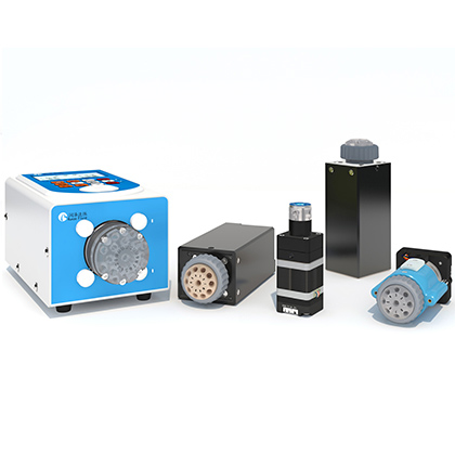
A syringe pump air gap can separate liquid segments in a multiport fluid path, but a field case showed the trailing liquid becoming dispersed after the air segment passed through a switching valve. The documented application used an SY-08 syringe pump with a 5 mL syringe and an SV-04 switching valve. The customer drew 200 uL from one port, discharged through another, then drew air from a third port and discharged it through the same outlet to separate the previously delivered liquid.
RUNZE reproduced the flow path and identified two practical controls in the source documents: use suitable high-quality PTFE rigid tubing and reduce pump speed according to the liquid and actual setup. The case report recorded an improved observation after changing the speed setting to a value written as 15 rpm/min, while the sales summary describes about 15 rpm. Because the units are not consistent across the two sources, the active protocol and command unit must be confirmed before the setting is reused. The engineering lesson is to treat the value as a case reference, not a universal recipe.
When a syringe pump air gap breaks up the trailing liquid after a switching valve, first reproduce the exact sequence and record the pump speed, liquid, tubing material and dimensions, air volume, valve positions, and whether the effect occurs every cycle. The RUNZE case improved the endpoint by using good-quality PTFE rigid tubing and lowering the speed. Start with a controlled reduction rather than assuming a pump or valve fault. Confirm the speed unit in the protocol, because the case report and sales summary do not use identical notation. If the effect remains, provide the flow diagram, settings, liquid information, and slow-motion video for technical review.
The customer configuration was an SY-08 5 mL syringe pump and an SV-04 switching valve. The customer description says 200 uL of liquid was drawn from port 1 and discharged through port 2. The valve then moved to port 3 to draw an air segment, returned to port 2, and discharged that air to isolate the liquid already delivered. The reported problem was dispersion of the isolated air segment and the trailing liquid.
The internal application case rebuilt the flow path with an SY-08 and a switching valve, connected one SY-08 5 mL pump at address 0 and an SV-04 six-channel valve at address 1 on RS485, and controlled them from a PC. In the reproduction sequence, the pump drew 500 steps of liquid, discharged through port 2, drew 500 steps of air through port 3, and discharged again through port 2. The report then compared the default-speed observation with a reduced-speed run.
The experiment is valuable because it preserves the sequence and the direction of change. It does not publish a universal acceptable dispersion limit, a validated range for all fluids, or a complete model relating density to speed. Data not available in source documents. Those limits must be determined for the actual instrument and assay or process.
A syringe pump air gap investigation should begin by separating repeatable sequence effects from component faults. The source guidance says to ask for the current speed, tubing type, liquid, desired outcome, and whether the dispersion happens every time or only occasionally. It also recommends recording the pump and valve models, a connection diagram or photo, tubing material and size, draw and discharge settings, liquid name and density, and a photo or video of the effect.
The same guidance warns against declaring the pump or valve defective before the speed and tubing are checked. That is appropriate for this case because the laboratory reproduction improved after those variables were controlled. It also warns that the setting should be adjusted to the actual liquid. The source does not provide a safe formula for converting density or viscosity into rpm. Data not available in source documents.
Test condition | Documented setup | Observed use in diagnosis |
Customer path | SY-08 5 mL plus SV-04 with liquid and air routed through port 2 | Defines the sequence that must be reproduced |
Communication | Pump address 0 and valve address 1 on RS485 in the lab case | Keeps device actions identifiable during replay |
Tubing | Good-quality PTFE rigid tubing recommended | Controls a documented hardware variable before fault escalation |
Default speed | Initial reproduction used the normal default setting | Trailing liquid and air-gap behavior were observed |
Reduced speed | Case report labels 15 rpm/min; sales summary says about 15 rpm | Improvement was reported, but the command unit must be confirmed |
Applicability | Speed should be adjusted for the actual liquid and setup | Treat the case value as a starting reference only |
1. Freeze the sequence. Record every valve position, draw and discharge step count or volume, pump speed, acceleration setting if changed, and the timing between valve movement and pump movement.
2. Identify the hardware. Record the exact SY-08 configuration, syringe capacity, switching-valve model and channel count, interface type, and device addresses. Do not assume the laboratory's six-channel SV-04 matches another installation.
3. Document the liquid. Record the liquid name and available density or viscosity information. If those properties are unavailable, do not substitute water values and present the result as equivalent.
4. Check the tubing. Record material, ID, OD, length, cut condition, and connections. The case specifically recommends suitable high-quality PTFE rigid tubing between the pump and valve.
5. Capture the baseline. Run the existing program without changes and record several cycles. Note whether the liquid breaks up before the valve, within the visible section after the valve, or only at the final outlet.
6. Reduce speed in a controlled step. The source case showed improvement at a lower setting. Confirm the protocol unit before entering the documented value, then change only speed and repeat the same cycle.
7. Compare video and cycle records. Use the same camera position and lighting so the amount and location of dispersion can be compared rather than judged from memory.
8. Escalate with evidence if the effect remains. Provide the flow diagram, exact sequence, settings, tubing information, liquid properties, and before-and-after video. Avoid repeated unstructured trial and error.
The pump catalog gives context for the SY-08 but does not turn the case into a universal operating limit. For the 5 mL configuration, it lists a 30 mm rated stroke with 12,000 control steps, a maximum speed of 600 rpm, a linear-speed range of 0.017 to 10 mm/s, and a control resolution of 0.0025 mm or 0.416 uL. It also lists liquid-volume error of no more than 1 percent at rated stroke and repeatability error of 0.3 to 0.7 percent at rated stroke.
Those values describe the pump under the catalog's stated conditions and should not be used to predict air-gap shape after a valve. The catalog notes that back-pressure curves were measured with pure water at room temperature and atmospheric pressure. The air-gap case involves a combined pump, valve, tubing, liquid, and command sequence. Keep pump specifications and system-level observations separate in the qualification report.
The important result is directional: the documented lower-speed run improved the trailing-liquid condition compared with the default-speed run. The report's label of 15 rpm/min is unusual for a rotational speed, while the associated sales-experience summary states about 15 rpm. The safest publishing and engineering practice is to disclose the difference and require confirmation against the active command set.
Do not copy the number into production code without confirming the device protocol, firmware, syringe size, and command definition. A setting that produces acceptable behavior in one liquid and flow path may not do so in another. The source explicitly says to adjust speed according to liquid density and the actual situation, but it does not provide a validated multi-liquid table.
If controlled speed and tubing checks do not improve the behavior, the sales guidance recommends collecting more evidence rather than making a remote diagnosis. It asks whether the effect is new or has existed since installation, whether particular valve positions are worse, and whether the acceleration parameters were changed. It also recommends a slow-motion video and, where available, pressure or motor-current information during valve action.
The source further notes that inspection involving valve disassembly should be handled through professional after-sales support. This protects the device and avoids turning a flow-path investigation into an uncontrolled mechanical change. No numerical rotor-stator torque limit or customer disassembly procedure is provided in the source documents. Data not available in source documents.
· Define an acceptable air-gap and trailing-liquid appearance before testing
· Use the actual liquid or clearly label any substitute fluid
· Record pump model, syringe size, valve model, port sequence, and device addresses
· Record tubing material, ID, OD, length, and connection method
· Confirm speed units and command definitions in the active protocol
· Test the baseline and each changed setting over the same number of cycles
· Save synchronized command logs and video where practical
· Escalate persistent or position-specific behavior with the complete evidence package
This checklist keeps the diagnosis tied to observable system behavior. It also makes it possible to separate a useful operating adjustment from a one-time visual impression.
In the RUNZE case, the effect was associated with the operating speed and tubing used in a pump-and-valve flow path. The source does not assign one universal physical cause for every system. Reproduce the sequence and control those variables before diagnosing a component fault.
The application report labels the reduced setting as 15 rpm/min, while the related sales summary says about 15 rpm. The lower-speed run improved the observed condition, but the unit discrepancy must be checked against the current protocol before the value is reused.
The case recommends good-quality PTFE rigid tubing for the tested arrangement. It does not state that one tube specification is correct for every liquid, valve, pressure, or instrument. Confirm tube size, compatibility, and connection requirements for the actual system.
No. The documented response specifically says not to declare a pump or valve fault before checking speed and tubing. If the behavior persists under controlled conditions, send the complete test record for technical review.
The source says speed should be adjusted according to liquid density, but it does not provide a validated calculation or lookup table. Data not available in source documents. Determine the setting through controlled application testing.
Provide the pump and valve models, flow diagram, tubing material and dimensions, liquid name and properties, air and liquid volumes or steps, speed and acceleration settings, valve sequence, occurrence rate, and a clear video.
No direct relationship is published. Catalog accuracy and repeatability are stated at rated stroke, while air-gap shape is a system-level observation involving the pump, valve, tubing, liquid, and sequence.
A syringe pump air gap should be troubleshot with the entire fluid path under a repeatable command sequence. The RUNZE case supports two first actions: use suitable high-quality PTFE rigid tubing and test a controlled reduction in pump speed. It does not support copying one speed into every system, especially because the source documents use inconsistent notation for the reduced setting. Confirm the protocol unit, record the liquid and hardware conditions, compare repeated cycles, and escalate persistent behavior with video and command data. That process turns a visual symptom into evidence that can guide a defensible pump-and-valve setting.


 English
 日本語
 한국어
 français
 Deutsch
 Español
 italiano
 русский
 português
 Türkçe
 Nederland