In automated fluid control systems, stable and reliable communication is fundamental for ensuring precise command execution and status feedback. When using an industrial computer or host computer to control SY series infusion pumps (such as SY-01B, SY-03B) via RS-232/485 communication, users may encounter the issue of "garbled return codes." This problem prevents the correct parsing of the pump's status parameters (such as current operation status, error codes, remaining volume, etc.), consequently hindering the host system from making accurate judgments and subsequent control commands, which severely impacts the continuity of automated processes.
This guide aims to provide systematic troubleshooting steps to help users quickly locate and resolve communication garbling issues.
1. Communication Foundation: SY series pumps typically support communication protocols like ASCII code and Modbus. Both communicating parties (the pump and the host) must have completely matching parameters – Baud Rate, Data Bits, Stop Bits, Parity Bit – to encode and decode data correctly.
2. Signal Integrity: Incorrect wiring (e.g., wrong pinout, reversed A/B lines), power supply interference, or poor-quality cables can lead to signal distortion, resulting in garbled codes.
3. Protocol Comprehension: Correctly identify the return code format. Return codes might be displayed in Hexadecimal or ASCII character form. Determining whether it is "true garbling" depends on the debug software settings and the format of the command sent.
SY Series Infusion Pump under test (e.g., SY-01B).
Stable DC 24V/3A±10% Power Supply.

OEM-provided or verified DB15 communication cable with correct pinout definition.
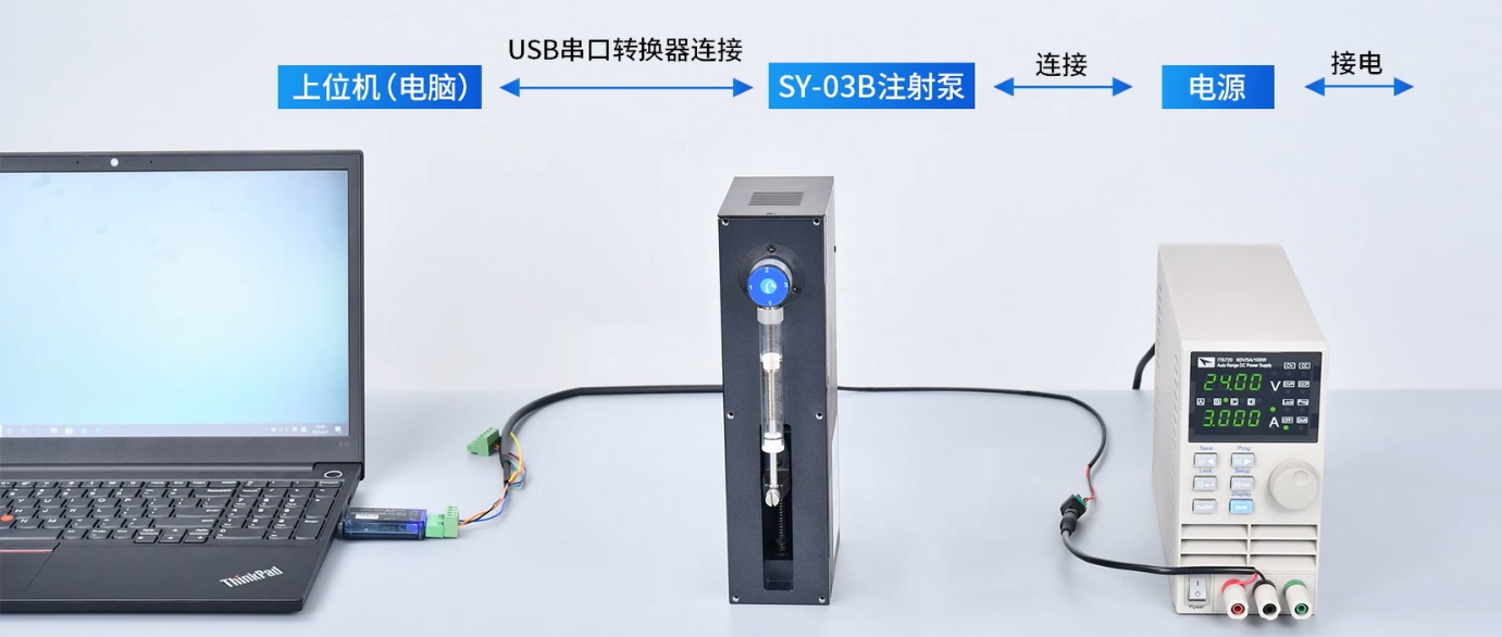
USB to RS-232/485 Converter (e.g., recommended USB-30 serial tool).

PC equipped with Serial Port Debugging Software (e.g., SerialComm, Friendly Serial Port Assistant, etc.).
Correct wiring is the primary condition for successful communication. Please strictly follow these steps:
1. Use Recommended Cables: It is strongly advised to first test using the manufacturer's original cable to rule out cable fabrication issues.
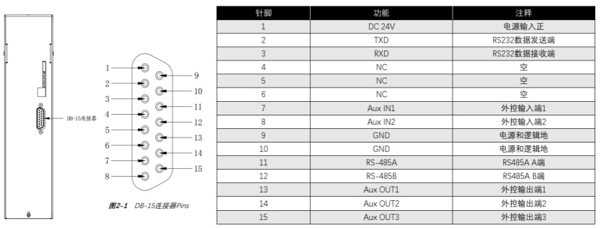
2. Verify DB15 Pinout Definition: If you must solder your own cable, strictly adhere to the DB15 pinout definition in the device manual.
RS-232 Wiring: Pump's Male RX connects to Converter's Female TX. Pump's Male TX connects to Converter's Female RX. Pump's Male GND connects to Converter's Female GND.

RS-485 Wiring: Pump's Male 485A connects to Converter's Female 485A. Pump's Male 485B connects to Converter's Female 485B.
Note: Power Ground (usually Pin 9) and Communication Ground (Pin 10) should be connected separately, not on the same pin.
3. Check Converter DIP Switches: Ensure the voltage and mode (RS-232/485) DIP switches on the USB-Serial converter are in the correct position.
4. Ensure Stable Power Supply: Use a compliant 24V DC power supply to avoid communication abnormalities caused by power interference.

1. Step 1: Reproduce in a Standard Environment
Use the OEM cable, recommended USB converter, and SerialComm debug software, connecting according to the product operation video.
Correctly set the serial port parameters in the software (e.g., 9600 Baud Rate, 8 Data Bits, 1 Stop Bit, No Parity).
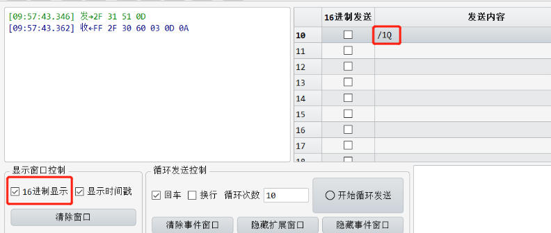
Send a simple query command, such as the ASCII protocol command /1Q.

2. Step 2: Determine if it's "True Garbling"
Observe the return code format and compare it against the standard return codes.
ASCII Protocol Return Code Example (Hex Display): Send /1Q (i.e., 2F 31 51 0D). The normal return should include a status code and have a regular format.

ASCII Protocol Return Code Example (Character Display): Deselect "Hex Display". The return code should be a readable string.
If the return code format does not match the standards above and the characters are completely unreadable, it can be judged as "true garbling".
3. Step 3: Check Software Settings
Verify Serial Parameters: Ensure the serial port parameters (Baud Rate, Data Bits, Stop Bits, Parity Bit) on the PC debug software match 100% with those of the pump. This is the most common cause of issues.
Check Protocol Match: Confirm that the sent command format matches the communication protocol currently set on the device (whether it's ASCII or Modbus).
4. Step 4: Cross-Testing
If conditions allow, try replacing the USB-Serial converter or testing with another pump of the same model to determine if the issue lies with the host side or the pump itself.
1. First Step: When garbled communication occurs, the first action should be to set up a standard test environment using the manufacturer's recommended cables, converters, and software. This helps determine if the problem originates from the user's environment or the product itself.
2. Key Checkpoints: If wiring your own cables, it is essential to rigorously verify the DB15 pinout and the RS-232/485 connection logic, and ensure stable power supply free from interference.
3. Final Solution: If the problem persists after following all the steps above and is confirmed as "true garbling," it is likely a fault in the pump's internal communication circuit. In this case, promptly communicate with technical support and arrange to return the device to the manufacturer for further inspection and repair.
By following this systematic troubleshooting approach, the vast majority of communication garbling issues can be effectively resolved, ensuring the stable and efficient operation of your fluid control system.