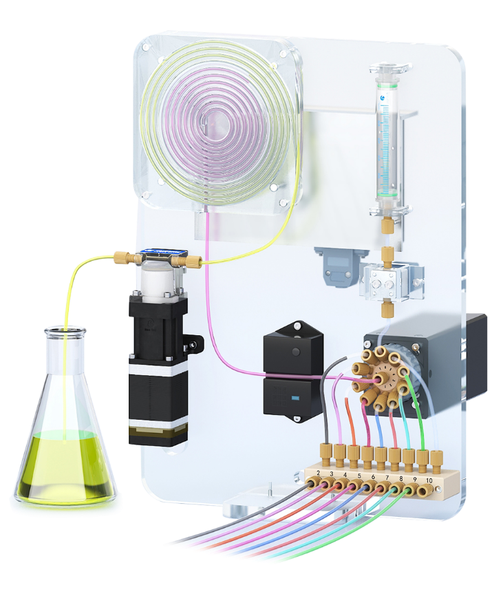
PS-10 non-cross contamination system was made of syringe pump or piston pump, multiport selector valve, two way solenoid valve, liquid level detector, chemistry reaction pool, tubing and fittings to create a full loop of working flow process to deliver multiple chemicals into the syringe pool for chemical mixing or reaction without cross contamination when transferring from one liquid to another, this will highly increased the safety and extended the lifetime of syringe pump and piston pump, thus reduce the maintenance cost for end users.
The instrument adopts the world's leading sequential injection technology, which sucks the test sample and reagent into a storage ring in a certain order through a plunger pump and a multi-channel switching valve, and then switches through the multi-channel switching valve and the reverse operation of the plunger pump. Moving the reagent in the zone towards the reaction chamber, where the sample and reagent are digested under high temperature and pressure. After digestion, the light absorption signal is collected and processed in the digestion tank. Then, after rapid cooling, the fluid is discharged through a multi-channel directional valve and the detected fluid is discharged into a waste liquid collection bottle. After cleaning the pipeline, a detection is completed. Throughout the entire process, the liquid storage ring is utilized, and reagents and samples do not come into direct contact with the syringe
a.High reliability and low maintenance
◆ Using the world's leading sequential injection platform, the reagent consumption is low, accounting for 1/20 of the conventional chemical method instrument reagent usage, making it suitable for long-term online monitoring
◆ High integration multi-channel switching valve, with a single valve body capable of switching between 6-16 valve positions, with a simple construction
◆ Innovative liquid storage ring structure, where samples or reagents do not come into direct contact with the syringe, avoiding wear and corrosion of the syringe flow path
b.Accurate measurement and wide applicability
◆ Adopting analytical methods consistent with national standards, industry standards, and calibration standards, suitable for automatic monitoring of chemical oxygen demand (COD) at environmental pollution source discharge outlets
◆ Sample and reagent volume quantification is accurate, with good repeatability, far higher than conventional chemical methods and instruments
◆ Unique bubble stirring mixing technology ensures thorough mixing of samples and reagents.
COD analysis is based on an oxidation method. Its quantitative analysis yields varying results depending on the type and concentration of the oxidant, the acidity, the reaction temperature, and the reaction time. (A strong oxidant is used to oxidize organic matter in water and calculate oxygen consumption.)
PS-10 System Principle: To prevent variability in results due to different oxidants and reagent concentrations, the entire flow path is air-blocked and the pipelines are promptly flushed with clean water to prevent cross-contamination between reagents.
① Test process
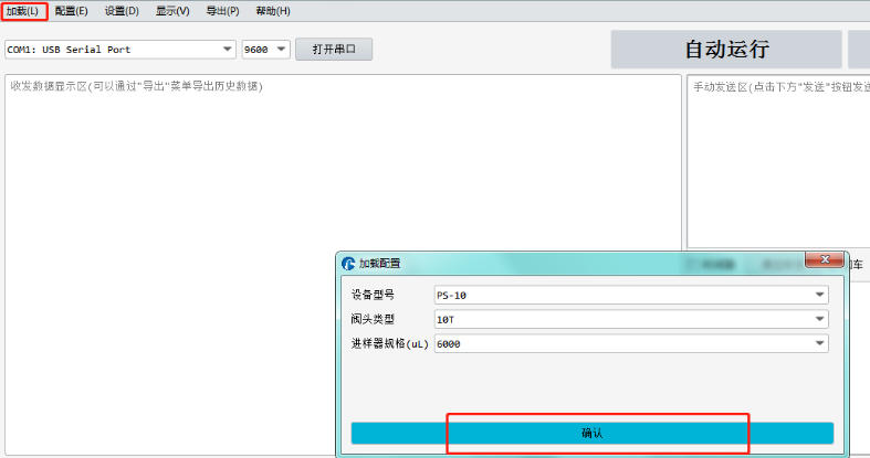
1."Load" the PS-10 configuration file.

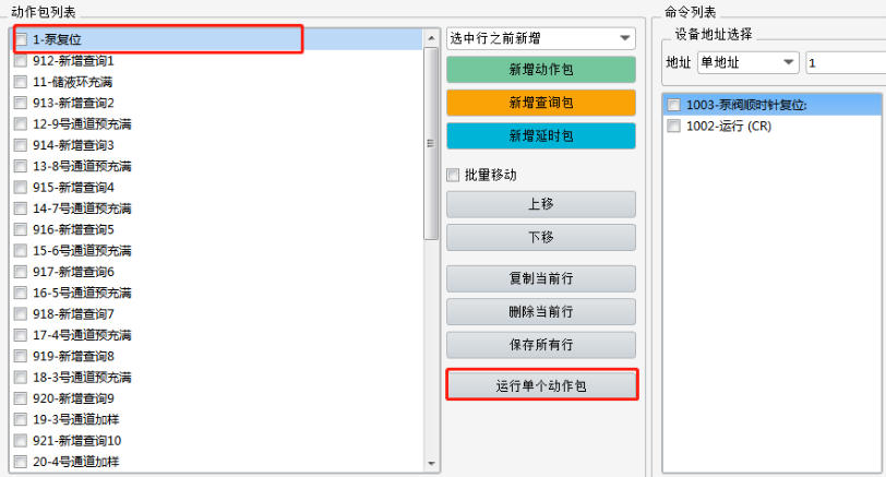
2.Then reset the pump valve of the PS-10 system through the corresponding instructions in the action package list.

3.After the reset is completed, fill the liquid storage ring first, and then pre-fill the required pipelines in sequence through the instructions. Then select the pipeline that needs to be added or all pipelines to add samples to the reaction pool one by one or in sequence (the volume of the reaction pool needs to be considered). After all the reagents have entered the reaction pool, the mixed waste liquid is completely discharged through the No. 2 waste liquid port, and then the entire pipeline is cleaned with clean water until the entire test is completed.
② Command analysis
Pump Valve Reset (/1ZR) Reservoir Ring Fill (/1I2gJ64V900A5000J32V900A0G2O10R) This command fills the reservoir ring with pure water to prevent test reagents from entering the plunger pump chamber and contaminating it.
Flow Injection (Using Channel 9 as an Example)
/1V80P299O9V82P2999I2V80D3135O9V80D100I2J64V400P1500J32V400D1500I10J64V400A0J32R
First, draw 0.235ml of air through the air port of Channel 10 to serve as a barrier between the pure water and the reagent. Then, draw 2.35ml of reagent from Channel 9 to pre-fill the reagent inlet. After pre-filling, some of the air in the common channel and all of the reagent, approximately 2.46ml, are discharged to the waste tank through Channel 2. Then, draw 0.078ml of air from the air port of Channel 10. This air is then pushed into Channel 9 to serve as a barrier between the reagent and the pure water, reducing contamination.
Flowline Sampling (Using Channel 3 as an Example) /1V80P299I3V80P4300M2000O2M1000V80D133O1J48V80D4000M1000O10V80P786I1V80D573J40I3V80D100O2J64V500P2000J32V500A0O10R
First, draw 0.235ml of air from Channel 10 to serve as a barrier. Then, draw 3.7ml of reagent (more than the required amount for the test) from Channel 3 into the reservoir loop. After the draw is complete, pump 0.1ml of the reagent solution into the waste port. Then, pump the required 3.4ml into the reaction cell. Finally, pump the remaining 0.2ml into the waste tank. Then, draw clean water to rinse the common line and drain the wastewater into the waste tank.
Mixing and stirring
/1O10V100A6666J48I1V100A0G2J32R
Introduce air into the reagents to tumble them continuously, accelerating mixing and reaction.
Waste discharge
/1gO10J32V400A2546J48I1V400P5093I2V400D7640J64V400P1500J32V400A0G3R
After the reaction is complete, drain all mixed reagents into waste tank No. 2.
Cleaning
/1gO1J16V900A6366J48V900A0G2I1V900P5730I2V900D5730gO1V900P5730I2V900D5730G2J64V900P1910O2J32V900D1910O10V900P150R
Pump a full stroke of clean water from the clean water tank and inject it into the reaction tank through the common port and port 1 to clean the entire reaction tank. The waste liquid is then discharged into the waste liquid tank through channel 2. Pump clean water again to clean the common pipe and discharge the cleaning liquid to waste port 2.