The peristaltic pump, renowned for its gentle, contamination-free operation, is a cornerstone of fluid handling in industries ranging from biotechnology and pharmaceuticals to food processing and wastewater treatment. Its principle is elegantly simple: a rotor with rollers or shoes compresses a flexible tube, creating a moving occlusion that propels the fluid within. This design isolates the fluid from the pump mechanism, making it ideal for sterile, abrasive, or sensitive fluids. However, this very strength is also the source of a common and critical failure mode: the stall, or more accurately, the rotor stall. This article presents a detailed case study of a peristaltic pump stall in a biopharmaceutical setting, analyzing its root causes, immediate consequences, and the strategic solutions implemented to prevent recurrence.
The incident occurred in a large-scale bioreactor facility for monoclonal antibody production. A critical process involved the continuous, metered addition of a concentrated nutrient media into a 2,000-liter bioreactor over a 10-day fermentation cycle. The pump in question was a sanitary peristaltic pump, chosen for its ability to handle the complex, protein-rich media without shearing the cells or risking contamination. The pump was equipped with a pressure sensor and a variable frequency drive (VFD) for speed control.
On the seventh day of a production batch, the process control system triggered a high-pressure alarm, followed by a pump fault. The pump had stalled. Investigation revealed that the rotor had ceased turning, despite the motor receiving power. The immediate consequence was the cessation of nutrient feed. This disruption lasted for approximately 90 minutes until a backup pump could be brought online. The nutrient starvation stress caused a significant drop in cell viability and altered the metabolic profile of the culture. The batch, representing millions of dollars in potential revenue, was ultimately scrapped due to failure to meet product quality specifications. The financial impact was substantial, encompassing the cost of raw materials, utilities, labor, and lost production capacity.
A thorough root cause analysis (RCA) was conducted, moving beyond the superficial "pump stopped" conclusion. The investigation identified three primary contributing factors:
1. Tubing Failure: The Primary Catalyst
The most direct cause of the stall was the catastrophic failure of the pump tubing. Instead of a clean rupture, the tubing had undergone significant plastic deformation and wall thinning, leading to a "gel-like" occlusion that the rollers could not effectively compress and move.
Material Incompatibility: The tubing was a standard silicone formulation. While generally compatible with cell culture media, the specific batch of media contained a higher concentration of a lipid-based supplement. Over time, this lipid component caused the silicone to swell and soften, significantly reducing its pressure-bearing capacity and resilience.
Excessive Operating Pressure: The pump was operating close to its maximum rated pressure. This high load, combined with the weakened tubing, accelerated fatigue. The constant compression and relaxation cycles generated internal heat, further degrading the tubing polymer.
Incorrect Tubing Selection: The facility had standardized on a single tubing type for all media feeds without considering the specific chemical composition of different media formulations.
2. System Design and Control Flaws
The tubing failure was the symptom; the system design flaws were the underlying disease that allowed the symptom to cause a stall.
Inadequate Pressure Relief: The system lacked a dedicated, mechanical pressure relief valve. The only protection was the electronic high-pressure cut-off in the VFD. This electronic safety has a inherent reaction time. By the time the pressure spike was detected and the motor was commanded to stop, the rotor was already jammed against the hyper-compressed, deformed tubing.
Lack of Torque Monitoring: The pump's VFD was configured only for speed control. It did not have a torque-limiting or monitoring function. A healthy peristaltic pump requires a relatively consistent torque. A sudden increase in torque is a clear precursor to a stall, caused by tubing deformation, increased fluid viscosity, or a downstream blockage. Without this monitoring, there was no early warning.
3. Procedural and Maintenance Gaps
Human and procedural factors played a significant role.
Fixed Tubing Replacement Schedule: The tubing was replaced on a rigid time-based schedule (e.g., every 5 batches) rather than a condition-based one. The RCA revealed that the media formulation change had shortened the tubing's effective lifespan, but the schedule was not adjusted accordingly.
Insufficient Operator Training: Operators were trained to respond to alarms but not to recognize subtle signs of impending failure, such as an unusual sound from the pump head or a gradual creep in the pump's amperage draw (a proxy for torque).
The post-incident corrective actions were comprehensive, focusing on creating a robust, fault-tolerant system.
1. Enhanced Tubing Management:
Compatibility Testing: A formal protocol was established for testing new fluid components with pump tubing. The standard silicone was replaced with a reinforced, lipid-resistant tubing formulation for this specific application.
Condition-Based Monitoring: Instead of a fixed schedule, tubing life is now tracked using a pump controller that integrates runtime, revolutions, and pressure cycles. Alerts are generated when the tubing approaches its predicted end-of-life.
Visual Inspection Guides: Clear guides with photos of acceptable vs. unacceptable tubing (showing swelling, wear tracks, deformation) were posted at all pump stations.
2. System Hardening with Redundant Safeties:
Mechanical Pressure Relief Bypass: A spring-loaded sanitary relief valve was installed in the discharge line, plumbed back to the feed tank. This provides an instantaneous, mechanical means to bypass a blockage and prevent a pressure spike from ever reaching the pump head.
VFD Reconfiguration: The pump's VFD was reprogrammed. Speed control remained the primary mode, but a torque limit was set. If the motor torque exceeds a predefined threshold (indicating a jam is imminent), the VFD automatically cuts power and triggers an alarm before a full stall can occur. This serves as a crucial early warning system.
3. Advanced Control and Monitoring:
"Pump Health" Dashboard: The supervisory control and data acquisition (SCADA) system was updated to include a "pump health" dashboard for critical feeds. It displays real-time torque, pressure, and efficiency (flow rate vs. speed), with trend lines to help predict failures.
Staggered Redundancy: For the most critical bioreactor feeds, a fully redundant pump skid was installed in a lead-lag configuration, ready to automatically take over if the primary pump faults.
The stalling of a peristaltic pump is rarely a simple mechanical fault. As this case study demonstrates, it is typically the culmination of interacting factors: a compromised consumable (the tubing), an inadequate system design (lack of mechanical relief), and insufficient procedural controls (rigid maintenance schedules). The financial and operational impact of this single stall was severe.
The key takeaway is that preventing peristaltic pump stalls requires a holistic, defense-in-depth approach. It is not enough to simply buy a high-quality pump. Engineers and operators must carefully consider fluid-tubing compatibility, design systems with both electronic and mechanical safeties, and implement intelligent, condition-based maintenance protocols. By viewing the pump, the tubing, and the control system as a single, integrated unit, reliability can be dramatically increased, protecting both valuable products and critical processes from the disruptive and costly consequences of a rotor stall.

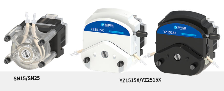
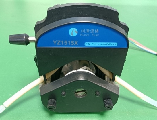
1. If the peristaltic pump fails to operate normally, open the pump head and remove the pump tubing to observe whether the motor operates normally under no-load conditions. Using the YZ1515X as an example, open the pull rod to place the motor in a no-load state and control the motor to operate.

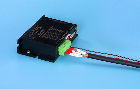
2. If the motor still stalls when no-load, check the motor cable sequence to see if it is correct and whether it is loose or falling off. Reconnect the motor cable and run again. If it does not run normally, send it back for inspection.

3. If the motor can run normally without load, it means there is no abnormality in the motor.
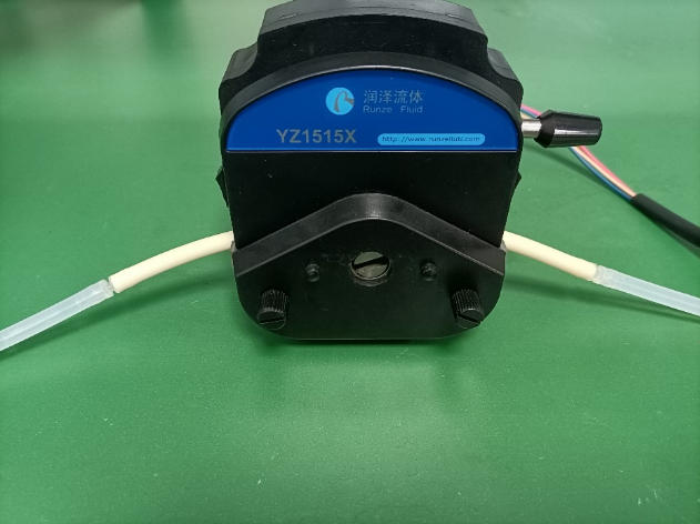
4. Pull down the pull rod, insert the pump tube and conduct a load test. If it can run, it means that the problem is with the pump tube installation.

5. If it does not work properly, if the customer's drive is our product, we will help the customer to modify the current. If not, we recommend the customer to contact the drive manufacturer.
1. Before use, we must inform customers of the motor's power and other parameters, as well as how to modify the driver's output current.
2. We recommend applying lubricant before initial use and after replacing the pump tubing. Operate the pump at a low speed to evenly distribute the lubricant across the rotor and tubing surfaces.
3. We recommend that customers regularly check the connection between the motor and driver for loose cables.